
The Scope of this work covers the following activities:
The excavation necessary for construction of Longitudinal Drain as per Section 300 MORT&H Specifications.
The selection of various construction materials, testing of materials, approvals and quarry selection, testing and approval of various grades of materials etc. conforming to section 1000 MORT&H Specifications
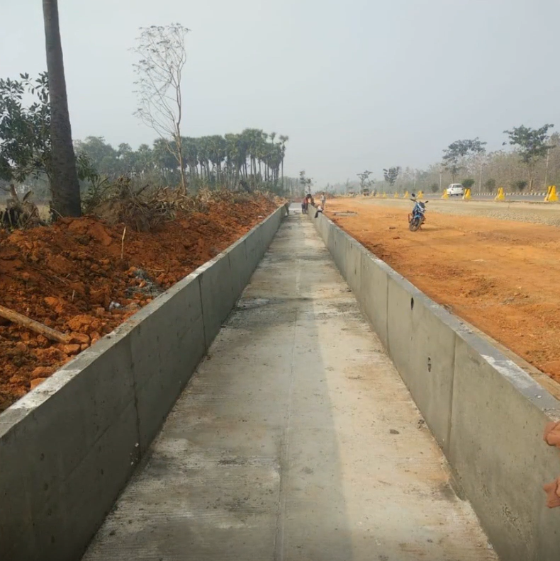
The construction of Longitudinal Drain with reference to, Section 300, Section 1000, Section 1500, Section 1600 and Section 1700 of MORT&H Specifications.
1.0 Materials
2.0 Plant, Equipment and Machinery
3.0 Construction Operations
3.1 Survey and Setting Out Works
3.2 Shop Drawing submission
3.3 Construction of Longitudinal Drain
3.3.1 Excavation
3.3.2 Bedding for Longitudinal Drain
3.3.3 Construction of Longitudinal Drain Base slab (Raft) by Cast-in-Situ Method
3.3.4 Construction of Longitudinal Drain walls – Stage 2
3.3.5 Construction of Longitudinal Drain by Precast Drain Method
3.3.6 Spreading, Compaction and Testing for Backfilling Material on both sides of Longitudinal Drain Backfilling behind Structure
4.0 Work Safety
5.0 Records
1.0 Materials:
• Ordinary Portland 43 Grade conforming to IS 8112, or 53 Grade Cement conforming to IS 12269.
• Coarse Aggregates, Sand / Fine Aggregates as per IS 383 and the tests shall be carried out as per IS 2386.
• The formwork material shall comply with IRC 87.
• Reinforcement steel bar shall be Fe 500 grade and conforming to IS: 1786.
• Water conforming to section 1010 MORT&H Specifications
2.0 Plant, Equipment and Machinery:
The following plant and equipment are necessary for the planned progress: –
a) Batching Plant.
b) Transit Mixers.
c) Needle Vibrators.
d) Slump cone and concrete test cube moulds.
e) Concrete Pump and Crane bucket.
f) JCB/Excavator.
g) Tippers/Dumpers.
h) Steel Shutters as formwork.
3.0 Construction operations.
3.1 Survey & Setting out Works
The limits for excavations shall be set out true to lines, curves, slopes, grades and sections as shown on the drawings or as directed by the Engineer and using established Bench Marks / Co-ordinates. All the Survey Instruments used shall be calibrated periodically as per the Calibration Plan. Survey Check Reports and other relevant data shall be maintained in relevant inspection formats.
3.2 Drain drawing submission
The drawing for the Longitudinal Drain shall be made with the Invert levels shown with the indication of type of bedding as specified on the working drawing.
Before any construction work is being carried out, the Contractor must submit an elevation of the Invert Level showing the length to be constructed and the following details to be incorporated on the shop drawing:-
• The existing ground profile.
• Founding levels at the base.
• Invert levels of Longitudinal drain from one point at downstream to upstream.
• The invert levels of the longitudinal drain intersecting the box culvert
• The Longitudinal drain bar bending schedule should be submitted together the shop drawing.
• The Engineer’s approval for the shop drawing and bar bending schedule should be obtained well in advance of the scheduled start date of the Longitudinal Drain.
3.3 Construction of Longitudinal Drain
3.3.1 Excavation
The foundation bed for the Longitudinal Drain shall be excavated true to the lines and grade as set out. It shall be executed to provide sufficient room for steel shutters.
3.3.2 Bedding for Longitudinal Drain
The bedding surface of filling area must be a firm ground of uniform density throughout the length of the drain. It shall be compacted and tested so that it is good for the PCC to be laid on it.
The bedding surface of cutting area shall be clean and free from loose materials. Then lay the PCC to required thickness and dimensions. The finished surface should be uniform in thickness.
3.3.3 Construction of Longitudinal Drain Base slab (Raft) by Cast-in-Situ Method
The base slab dimensions shall be marked on the PCC.
After the above step is satisfactorily completed, fix the base slab reinforcement which were cut and bend in conformity with the bar bending schedule. Concrete covers shall be uniformly spaced at the bottom to support the reinforcement.
Clean up any debris in the PCC by blowing out any foreign materials not permitted.
All temporary shuttering shall be checked so that they are securely fixed.
When the approval to go ahead with concreting is obtained from the Engineer, order the calculated quantity of concrete for the pour.
The concrete should be uniformly vibrated with a needle. Conduct the routine slump checks and make test cubes as directed by the Engineer.
25mm Expansion joint gap to be provided at every 40 m interval to be filled with Salutex board and filler material (water proof).
Upon completing the concreting it is essential to cure the concrete with potable water on the next day and regularly do so for the next 7 days.
3.3.4 Construction of Longitudinal Drain walls – Stage 2
1.Tie the wall reinforcement which were cut and bend as per the bar bending schedule. When the Contractor is satisfied that the preparation is ready for inspection, submit a request to the Engineer for reinforcement inspection by raising a RFI.
2.Fix the steel shutters forms for the walls for stage 2 concrete after obtaining approval from the Engineer on the wall reinforcement. The steel shutters must be properly fixed and fastened together. Attention must be given to external lateral bracings are sufficient and would prevent bulging of concrete. Check that all gaps between steel shutters are properly plugged to prevent leaking of concrete slurry during vibration of the concrete. Next, when the Contractor is satisfied that the preparation is ready for inspection, submit a request to the Engineer for inspection by raising a RFI.
3.The Engineer carries out his inspection and approval given to proceed. Order, pour and vibrate the concrete in an acceptable manner specified by MORT&H Specifications. The concrete should be uniformly vibrated with a needle. Conduct the routine slump check and make test cubes as directed by the Engineer.
4.Upon completing the concreting it is essential to cure the concrete with water the next day regularly and continuously for the next 7 days.
3.3.5 Construction of Longitudinal Drain by Precast Drain Method
1.The base of the drain shall be formed with sand compacted to the required gradient.The drain centre line shall be maintained with the use of a string tied to wooden pegs from the downstream end to the upstream end.
2.The precast drain already lined up along the edge of the trench shall then be lifted by a JCB, equip with two steel rope (or acceptable slings) for lifting, and put in place in the trench.
3.The string shall be the guide in installing the precast drain unit from downstream to upstream.
4.The joints between drains shall be sealed with cement/sand mortar.
5.The next step is to construct the upper part where the reinforcement has been left for overcoming variation in depth of the Longitudinal Drain. This portion of work shall be constructed by the cast-in-situ method described in 3.3.3.
3.3.6 Spreading, Compaction and Testing for Backfilling Material on both sides of Longitudinal Drain
1.Back filling behind the drain shall be carried out as per the Clause 305 in MORT&H.
2.Back fill materials from approved Borrow areas will be spread in Layers to get 150 mm compacted thicknesses for the required length and width.
3.The required Cross Slope and Gradient shall be maintained as per drawings.
4.In areas where using vibratory rollers is not possible to carry out the compaction, suitable means like mechanical tamper, rammer, plate vibrator etc. shall be used for the compaction.
5.The frequency of testing and the type of tests to be conducted on compacted Backfill behind structures shall be as per MORT&H Specifications.
4.Work Safety Plan
The construction area occupied by the longitudinal drain shall be cordoned off from other earth moving plant working in the vicinity with warning tape. The contractor’s site safety team must conduct regular checks to see that the safety put up is in working condition at all times.
If concrete pouring has to continue beyond daylight, proper lighting should be organized ahead and standby for use when necessary.
Safety will be provided as per location specific safety plan.
6.Records
All records should be carefully documented and kept on all items of works so that when making payment to the Contract it is in order.