PILING METHOD STATEMENT

When the soil intended for the foundation is not capable of supporting a structure , deep foundations are required to transfer the loads to deeper strata. A pile is a slender structural member made of steel , concrete or wood.These days piles are more in trend rather than in well foundation .In this article we will discuss the typical method statement pertaining to pile.We had divided the method statement into 7 sections for easiness

1.Scope of Work

  1. Equipment
  1. Material
  1. Method Statement
  1. Tolerances
  1. Routine Test
  1. Integrity Test
  1. Scope Of Work This work consist of Pilling work -1200 mm dia. Bored piles Boring and Installation of 1200 mm dia .
  1. Machineries/Equipment  The following machineries shall be deployed at each working site.
  • Rotary rig -3
  • Augur of 1200  Size -3 Nos.
  • Drilling bucket of suitable size -3
  • Cleaning bucket (skip bases) -3
  • Crane 20 ton capacity -3
  • Slurry sampler -3
  • Metallic chain 25 m-3
  • Steel tape 30 m & spirit level plumb- 1 set at every site of
  • Jar& bucket and hydrometer – 1 set at every site of
  • Steel plate circular liner 6 mm thick and 5 m long -2  at every site or as required.
  • Steel rectangular tank of 20,000 litre capacity each -3 at each site,
  • Bentonite agitator with 3 HP motor -1 No at each
  • Flushing pumps 5 HP capacities -2  at each site.
  • Diesel pump 10 HP standby -1 No
  • Water tanker -1 No
  • JCB-1 No
  • Dumper/Tipper-2
  • Generator 62 KVA -1
  • Welding Transformer -2
  • Tremie pipes 200 mm  of different lengths as required for proper concreting.
  • Hopper 4 M³ capacity with plug at each site.
  1. Material

3.1 Bentonite – The betonite (drilling mud) shall be arranged of approved quality and shall be stored about 30 cms in water tanks  , 5% of bentonite by weight of water may be used subject to ensuring appropriate density

  • Density of suspension               =1.05 gm/cc
  • Silt content                                    = <1%
  • PH value                                          = 5 -12
  • Liquid Limit (not less than )  = 400

3.2 Concrete

  1. Grade of concrete                                 = M 35
  2. Slump                                                        = 150 -200
  3. Temperature                                           = < 40°c
  4. Minimum cement content               = 400 kg./ M³
  5. Maximum size of Aggregate           = 20 mm

3.3 Reinforcement

  • T.M.T bars FE 415/500 shall be used. Reinforcement cage shall be fabricated after cleaning as per approved bar bending schedule.
  • Stiffeners as show in the drawings. and cover blocks prepared out of non – shrink mortar of approved quality shall be provided and reinforcement shall be tied with 18 SWG binding wire and welding may be done only where necessary after providing suitable lap length. The clear cover of 75 mm shall be kept.
  1. Method Statement

4.1 Layout

  • The layout of piles shall be carried out with the help of Total Station only.
  • Grid /axis lines shall be established by total station as shown in the approved drawings and four Nos. reference points for each pile shall be established, in such a way so that these do not get disturbed during  piling work.
  • The ground levels shall be recorded with the help of auto level and the length of the piles shall be evaluated.
  • The nomenclature of pile group shall be designated clock wise or Anti              clock wise with specified location mentioning grid /axis.

4.2 Procedure

  • The pre-trenching shall be carried out to detect the utility (if any). Manual trenching in transverse and longitudinal direction shall be done near pile location up to about 2 m in depth or as required.
  • A circular pit shall be dug out for outer dia for steel casing manually for a depth of 1 m. The centre of pit shall be checked accurately from reference points.
  • Drilling by auger up to depth of casing shall be done.The steel casing shall be fixed with the help of rotary rig collar guide, truly in centre of hole as well as vertical.
  • The verticality of Kelli bar shall be checked by spirit level in two directions at bucket top level.
  • The casing shall be checked by plump bob also.
  • The verticality & levels are seen in cabin of Rotary Rig at Instrument display board.
  • Beyond casing depth of 5 m the drilling bucket shall be used.
  • The bentonite shall be mixed in tank mature for at least 8 hrs. before actual use and during feedings it shall be agitated.
  • The density of bentonite shall be checked during boring.
  • Verticality and depth shall be recorded as per Rotary Rig panel board.If it is not so, suitable measures shall be taken to rectify tendency of the bore to go beyond the centre point.
  • The cleaning bucket / skip box shall be used for the last 30 cms depth to achieve required founding level and for cleaning of mud.
  • The sounding shall be taken by using metallic chain.
  • The soil strata shall be recorded at every 3 m or at the change of strata.
  • Soil samples shall be kept for record in polythene bags marking the depth and pile no.
  • If there are chances of bore collapse, extra liner shall be provided upto a suitable depth.

4.3 Acceptance limits

  • Verticality – It shall not exceed 1 in 50.
  • Shift – The resultant shift in any direction from the location designed at cut off level shall not exceed 50 mm and shall be measured at pile cut off level.

4.4 Movement of Rig and Machines

The sequence of concreting of pile would be such that reference pillars are not damaged during movement or rig /machines.

4.5 Clearing of Bore Hole and flushing

  • The reinforcement cage duly welded at joints shall be lowered by crane. The cage shall be kept at the requisite level by suspending from collar.
  • Cleaning of the bore hole shall be done by the circulation of bentonite slurry of 1.05 gm/cc under high pressure through tremie pipe, which shall be kept max 150 mm above the bottom of bore.
  • During flushing the bentonite slurry shall be agitated and sufficient quantity of Bentonite Slurry shall be available.
  • This process shall be continued till the slurry at the bottom is of density 1.10 gm/cc .However care shall be taken to avoid bore collapse due to excessive flushing.
  • The slurry sampler shall be used to take the sample from bottom of the bore.
  • Concreting shall not be done, if density of bentonite slurry from bottom is more than 1.10 gm/cc.
  • The bentonite slurry carried out from bore, shall be pumped to next container so that the mud settles down.
  • The dugout earth and muck shall be removed immediately, and disposed off at approved disposal areas.
  • There shall be no over flow of slurry on road of working space.

4.6 Concreting

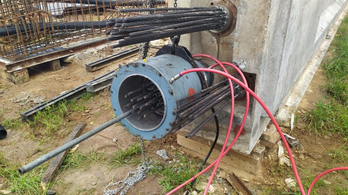
  • Concreting under water shall be placed in on continuous operation by tremie pipe So that concrete entering the tremie pipe shall not get mixed with the slurry.
  • The tremie pipe of minimum 200 mm dia with water tight joints using rubber seal shall be kept 200 mm above bottom of hole with attached hopper of 0.4 M³ capacity duly held by crane of 20 T capacities.
  • The approaches for movement of transit mixers shall be kept clean with suitable ramp near bore for easy pouring of concrete.
  • The 3 nos. of transit mixers shall be sufficient to maintain continuity of concrete, so that there shall be no interruption. The rate of pouring concrete shall be approximately 6M³ /hour.
  • First charge of concreting shall be done by using a stopper at the bottom of funnel. Stop shall be kept in such a way that it can be removed with least resistance.
  • The tremie pipe bottom shall be done by using a stopper at the bottom of funnel.
  • Pieces of tremie pipe shall be removed as per calculated depth of concrete. It shall be ensured that the end of the tremie pipe should always be in concrete to avoid slurry and muck mix with concrete.
  • If the delay during concreting is more than 2 hrs Cement slurry shall be used for mobilizing concrete inide the tremie pipe.If concrete pouring is delayed due to any reason.
  • The bentonite slurry shall be re-circulated to avoid settlement of suspended particles of earth. The sounding shall be taken after each load of concrete.
  • The slump test and concrete cubes shall be casted from each transit mixer as specified for concrete work.
  • The actual quantity of concrete if less than 10% of theoretical consumption shall be immediately reported to EIC.
  • The length of concrete above cut off level shall be at least 1.00 m.

4.7 Removal of guide casing

  • Casing shall be extracted by smooth pull and push movement.
  • Precaution shall be taken that concrete and reinforcement are not disturbed.

4.8 Breaking of pile head

  • The breaking of extra concrete shall be done after a minimum of 7 days of concreting.
  • The breaking can be done by pneumatic jack hammer or manually as per Direction of Engineer in charge.
  • The pile shall be cut off as indicated on drawing
  • The exposed reinforcement shall not be damaged while breaking the pile head concrete.
  • All dismantled material shall be disposed off at approved disposal areas.
  • The height for 150 mm above cut off level shall be chipped off manually to avoid damage to pile.
  1. Tolerances
  • Variation in diameter + 50 mm -10 mm
  • Variation from vertical -1 in 50
  • Variation in final position of head in plan =50 mm
  • Variation in level of top of pile +25 mm
  1. Routine Test
  • General arrangements for routine vertical test shall be made according to IS 2911 (P-IV).
  • Routine load test shall be carried out for 1.5 times of working load to determine the Safe load on pile.Safe load on pile shall be 2/3 of the load at which settlement is 12 mm.
  • The pile to be tested shall be selected by Engineer in Charge from any working pile groups.
  • The pile shall be tested after concrete achieves designed concrete strength.
  • Datum bar made out of MS Channels of size 125 mm shall be fixed on both side of the main girder such that the clear distance between the supports is at least a distance of 3D (D being dia of pile ) from the edge of the pile. Care shall be taken to ensure that the Datum bars do not get disturbed during loading.
  • Breaking of false concrete shall be done upto a level 50 mm above cut off level. The pile head shall be build up using non – shrink mortar.
  • The sub grade shall be built upto required level by properly compacting. approved kentledge arrangement shall then be placed in position,
  • Placing of base slab and concrete blocks upto required width and level shall be carried out.
  • Bottom and top plate shall be placed over jack and stool packing packing plate if required shall be used to fill the gap between main girder and jack
  • Placing main girder over concrete blocks after maintaining required gaps for settlement of secondary girders.
  • Level and weld the kentledge wherever necessary concrete fill shall be done in gap of concrete block and base girders.
  • Loading of blocks shall be done in layers as per drawing upto required test load plus 25% extra.
  • Concrete block in alternate layers shall be secured with 16 mm Ф wire rope and turn buckle after erecting scaffoldings.
  • Adequate precaution shall be taken for safety of adjacent traffic viz placing caution boards, barricades, blinkers, flags etc.
  • Four nos. dial gauges (deflect meters) shall be fixed from datum bar at four corners of the pile head. The least count of these shall be 0.001 mm
  •  All the pressure gauges, dial gauges shall be tested and calibrated before use.
  • Increment of load shall be @ 20% of design load .
  • Increment of test load and displacement in each stage of load shall be maintained till rate of displacement of pile top is either 0.1 mm in first 30 min. or 0.2 mm in the first Hour or till 2 hrs which ever occur first.
  • The final load of 1.5 times the design load shall be maintained for 24 hrs.
  • The load shall be released and rebound shall be recorded.

Integrity Test

  • Pile integrity test shall be carried with electronic analyzer.
  •  The test shall be carried out by approved agencies.
  • The test shall be carried out on 10% of working piles.
  • Records shall be submitted with recommendation.

Facebooktwitterredditpinterestlinkedinmail

METHODOLOGY FOR PRESTRESSING

The technique of precasting is eminently suited to  bridge girder for quicker construction and minimum interference to traffic below the bridge. The girder my be cast in a central plant or in a temporary yard established near the work site. Girder upto about 40 meter can be precast in a single piece transported to site by means of truck cranes.In this article we will discuss pertaining to stressing and prestressing of girder methodology.

REFERENCE DOCUMENTS/CODES/DRAWINGS

1.MORT&H 5th Revision
2. IS: 14268 Stress Relieved Low Relaxation 7 Ply Strands for Prestressed Concrete.
3. IS: 210 Grey Iron Casting – specification
4. BS: 970 Specifications for Wrought Steels for Mechanical & Allied Engineering Purposes.
5. IRC: 18-2000 Design Criteria of Prestressed Concrete Road Bridges (Post-tensioned Concrete)
6. Relevant Prestressing Drawings (Latest Revisions)
7. Specifications Related to Prestressing Work

PRESTRESSING MATERIALS

• High Tensile Strands
Following are the properties of 12.7 mm Ø Low Relaxation High Tensile Strands. Oiled strand shall be used –

Nominal Area of Strand – 98.7 mm 2
Minimum Breaking Strength – 183.7 KN
Nominal Weight of Strand – 0.775 kg/mtr.

• SHEATHING PIPES

We are giving typical sheathing pipe , use pipe as per your project specification
84 mm ID & 98 mm OD & 2 mm thick HDPE sheathing pipes for 19 DP13
75 mm ID & 90 mm OD & 2 mm thick HDPE sheathing pipes for 12 DP13
51 mm ID & 64 mm OD & 2 mm thick HDPE sheathing pipes for 7 DP13
Sheathing duct shall be made up of HDPE of thickness (2.3 mm ± 0.3) mm with following properties –

• Approved 19 DP 13,12 DP 13 & 7 DP 13 Live end Anchorage System(Use Project approved brand)

The precast segment will be cast in casting yard. After curing is over, the segment will be shifted to the respective position and will be assembled with the help of launching girder. The high strength epoxy will be used for gluing two segment together and it will be stressed by high tensioned bar. After final stressing, temporary stress will be released

Tube Unit (Anchor Cone)

The basic raw material for manufacture of tube unit is gray cast iron. It allows the transfer of prestressing force from the bearing plate to the concrete. The Tube Unit is embedded in concrete and can be easily fixed to the MS cone box by means of bolts and nuts. The design of Tube Unit allows uniform flaring of H. T. Strands while stressing and free access to the injection of grout.
Anchor Head (Bearing Plate)

The basic raw material for manufacture of bearing plate is Steel casting / forged steel. The conical holes facilitate the seating of wedges and holding the strands in stressed condition.

Wedges
The basic raw material for manufacture of wedges is alloy steel. The individual high tensile strands passing through the bearing plate is anchored by the wedges. The 3 segments of the wedges are held together around the strand by means of special wire circlips for better functioning, easy placement and storage

Prestressing and Grouting is broadly divided into following activities, viz.,

1. Layout & Profiling of the cables/sheathing.

2. Fixing of tube unit/end block.

3.Concreting

4. Cable cutting and threading.

5.Fixing of Bearing plate & Wedges.

6. Stressing.

7. Cutting and end Sealing.

7. Grouting.

1. LAYOUT & PROFILING OF SHEATHING PIPES

After completion of alignment of bottom shuttering & bottom reinforcement of girder, layout & Profiling of cables shall be carried out in following steps :

• Layout of cables is carried out as per given ordinates & related reference drawings.
• After all ordinates are plotted, tie bars of 10 mm. dia. shall be installed as per ordinates to place the sheathing pipe wherever required. Installation of sheathing pipe is carried out over the tie rods.
• Sheathing pipe shall be supported in the bottom by tie rods & shall be cross bound using double binding wire. It should be ensured that the sheathing pipes are fixed firmly in position so as to prevent displacement during concreting by weight of concrete, vibration or by floatation.
• Connect the sheathing with the help of couplers provided at the end of each pipe.
• Sealing of sheathing joints will be done using PVC tapes. It will be ensured that no joints are remaining unsealed.
• Cable profile shall be checked. Vertical ordinates shall be check from soffit of the bottom shutters. Horizontal ordinates shall be check from the face of the side shutters, which has been already checked for verticality or as in drawing.

2. FIXING OF TUBE UNIT

• Fixing of tube unit shall be carried out after installation of end shuttering plate.
• Fix tube unit to End plate with the help of 4 nos. of bolts.
• Bursting reinforcement shall be fixed according to the drawing.
• Connecting the tube unit to sheathing pipe.
• Joint shall be sealed with the help of PVC tape.
• The face of the tube unit shall be truly perpendicular to the axis of the cable and about 1.5 m of cable before trumpet should be in straight alignment.
• After the fixing of tube unit and cable layout, insert the HDPE pipes Or HTS Strand inside all ducts to avoid the damage of sheathing pipe & ingress of cement slurry inside the duct at the time of concreting.

3. CONCRETING

• Although concreting is not a part of stressing but it has very important role in successful completion of stressing of structure.
• It shall be noted that the needle vibrator is not placed directly on sheathing pipe, which may damage the sheathing pipe.
• HDPE pipe Or HTS Strands in all the cables should be moved in both directions during the period of concreting.
• More attention should be given while concreting in the end block portion. Adequate compaction of concrete to be ensured to avoid any kind honeycombing.

4. CABLE CUTTING & THREADING

After completion of concreting & removing end block shuttering, cable threading shall be done.
• H. T. Strands shall be threaded manually.
• For cutting strands, a portable grinding wheel shall be used.
• H. T. Strands shall be cut as given in drawings, considering site conditions & gripping length of jack.

5. FIXING OF BEARING PLATES & WEDGES

• Fixing of bearings plates & wedges is done before stressing. It is ensured that the tapered holes in bearing plates & wedges are free of rust.
• Insert the strands into the tapered holes provided in the bearing plate.
• Install the wedges over the strands and push them with a pipe into the tapered holes of the bearing plate.

6. STRESSING

Prestressing of the girder is done as required by the system of prestressing and design. Following points will be observed while carrying out the stressing operation.
Only trained and experienced personnel, under the guidance of  technical Staff, should perform stressing & grouting.
• The required strength of the girder concrete as mentioned in drawings/specifications shall be ensured by cube testing before starting the stressing work.
• Stressing of cables shall be done as per the sequence mentioned in the drawings/specifications.
• The first stage stressing shall be done after the concrete achieves 35 Mpa strength or 10 days after casting, whichever is earlier. In the first stage two cables shall be stressed viz. cable no. 1 & cable no.2  or as shown in the drawing.
• In the second stage stressing balance two cables i.e. cable no. 3 & cable no. 4 shall be stressed after the concrete achieves 45 Mpa strength (28 Days strength ) or 21 days after the casting, whichever is later
• Elongation mentioned in the drawings must be modified for actual value of modulus of elasticity ‘E’ and the area of c/s of strands ‘A’ of the cables as per the results unless otherwise mentioned in the drawings/specifications.
• Actual pressure shall be calculated after applying Jack efficiency factor.
• Stressing shall be done using Multi-pull jacks only.
• Stressing shall be done from both ends, care will be taken to achieve almost equal readings of elongation at both the ends in each step of increment of pressure.
• Readings will be taken preferably at incremental steps of 50 kg/cm2 up to the final pressure.
• After locking the wedges the pressure in the jack will be released very slowly to avoid transfer of prestressing force by impact.
• In every cable instantaneous slip of anchorages must be recorded. It will be within limits prescribed by the designer or by the prestressing agency.
• The pressure applied and elongation achieved will match within the prescribed limits. Normally, the limit is 5% of pressure and elongations.
• No person will be allowed to stand behind the anchorages in any circumstances during the process of tensioning.

6.1 THE FOLLOWING STEPS SHOULD BE PREFERRED FOR JACK MOUNTING 

  • Fix the bearing plates at both the ends of the tensions.
  • Insert the bearing collar & fix it on tube unit with the help of screws.
  • Insert the lock-off plate as per the orientation the bearing plate.
  • A rigid runaway beam (ISMC/ISMB) structure shall be made at the end of the bridge girder from where the Jack is to be suspended by means of a chain pulley block. The arrangement will give full flexibility of movement of Jack both transversely and longitudinally.
  • Push the Jack over the strands. The axis of the Jack must coincide with the tendon axis. Insert the strand in to the Jack.
  • Apply “wax” inside the holes of pulling plate as well as outside of master grip.
  • Install the 3-piece wedge (master grip) over the strand into the pulling plate inside the rear of the Jack. Push the grips with a piece of hollow hammering pipe to seat tightly inside the pulling plate holes.
  • Ensure all connection of Jack with pump is correct and flexibility of hose pipe for movement of the Jack at the time of stressing.
  • It is important that the supporting chain or hook shall be slackened off as soon as the Jack starts to carry load, but they must be ready to support the Jack again when the pressure is released.
  • Locking pressure should be maintained approximately 70-80 % of the stressing pressure.

7.0 CUTTING AND END SEALING

Cutting should be carried out after checking the 24 hrs. slip loss. Strand should be cut approximately 40 mm. from the face of bearing plate. End sealing should be done with the help of GROUT CAP or Epoxy & cement  Mortar (Mounting the ends) .

7.1 GROUT CAP :

 The advantages of using Dynamic Grout Cap are used for speedy grouting and saving of sealing material i.e. cement mortar.

 7.2 FIXING OF GROUT CAP

  • The stressed strands are cut to the required length i.e. 40 mm. from the face of bearing plate.
  • On the inner surface of cap, grease should be applied.
  • ‘O’ ring should be placed in the slot provided along the periphery of the cap, which maintains the pressure and prevents the leakage of grout.
  • Grout cap is fixed by 4 nos. of allen key bolts by keeping the air vent nut in top position.
  1. GROUTING

Neat cement slurry should be filled in the annular spaces between sheathing duct & high tensile (H.T.) steel/strands.

8.1 OBJECTIVES OF GROUTING :

1.To protect the steel against corrosion.

2.Effective bond between the Prestressing steel and concrete.

8.2 MATERIALS FOR GROUTING :

(A) CEMENT:

Ordinary Portland cement should be used for the preparation of the grout. I. The cement shall have no false setting phenomenon and shall be at a temperature less than 40 °C at the time of production of grout. The cement should be free from chemical impurities like chloride and sulphate, which leads to corrosion of steel.

(B) WATER:

Clean potable water, free from impurities shall be used. Sea or Creek water shall be strictly avoided.

(C) ADMIXTURE :

While designing grout mix , we are using Sika (Intraplast N 200) 0.4 % by weight of cement). to reduce shrinkage of grout.

 8.3 WATER – CEMENT RATIO

Choose Water-cement ratio as low as possible , consistent with workability. This ratio should not normally exceed 0.45. We are keeping 0.39 as per site condition.(Can select W/C ratio as per your convenient)

8.4 GROUT TEMPERATURE

Generally, the temperature of the grout must be 25 °C. It is likely to change depending upon the site conditions. When the ambient temperature during the day is likely to exceed 40 °C, grouting shall be done in the early morning or late evening hours.

 8.5  TESTS ON GROUT MIX

The characteristics of the grout are determined on the grout itself or on samples made from the grout in accordance with the following.

  • Fluidity
  • Bleeding
  • Volume Change

8.6 GROUTING PROCESS

 Following points will be observed while doing the grouting.

  • Grouting of cables shall be done as early as possible, after completion of stressing.
  • All cables that are to be grouted shall be cleaned thoroughly with water & compressed air.
  • The grout mix is prepared in the agitator by thoroughly mixing it for 1 min.
  • The agitator must be placed at a height such that mortar can flow directly in top second tank placed beneath the outlet of agitator.
  • Before flowing in to the second tank mortar must be passed through a 2 mm. mesh screen so as to eliminate impurities and lumps which otherwise cause choking of the pump at the time of grouting process.
  • Connect the suction hose of grout pump to the second drum.
  • Operate the pump to drain off water from the pump and hoses.
  • Allow discharge of a small quantity of grout from delivery hoses to check the correct functioning of pump.
  • Connect the delivery hoses to the tube unit’s grout inlet opening and begin grouting.
  • Ensure that there is always enough grout in tank so that air is not sucked in to the pump.
  • When the grout flows out of the dead end tube unit’s grout opening, open the air vent nut of the grout caps of both the ends.
  • Block the outlet of the other end after being assured that the air has been completely bleeded and the duct is filled with grout.
  • Close the air vent nut and operate the pump until the desired pressure is achieved.
  • After the design pressure is achieved, stop the pump and maintain the pressure of 3-5 Kg/cm2 for 1 min. and close the valve of inlet connector.
  • Release the pressure in hose. The pump runs idle and returns grout to the tank.
  • Clean the grout pump & agitator with clean water to z avoid clogging.

  8.7 END PROTECTION OF ANCHORAGES

 Tendons shall be protected against corrosion by a plug at each end  to prevent passage of air. After grouting is over the anchorages will be  protected for corrosion as under –

  1. Clean the exposed anchorage parts for rust and dirt with wire brush manually.
  2. Clean the surface with cotton waste & apply a coat tar epoxy (solvent free araldite)

9   SAFETY PRECAUTIONS

 9.1  Safety Precautions While Concreting

Although concreting is not a part of prestressing, it plays a vital role in successful stressing of structure. Following points should be considered while concreting

  • Main contractor should ensure that vibration is to be supervised. It should be noted that needle is not directly placed on sheathing pipe, which may damage the duct & thereby blocking the path of strands.
  • The portion of the end block of the girder should be properly concreted. Weak concrete leads to puncture of tube unit & hence stressing should be done only if concrete is capable of taking the load.
  • It should be ensured that the bursting reinforcement in the end block zone is adequately & properly installed.

9.2  Safety Precautions While Stressing

Very large forces are introduced into the tendons during stressing and the equipment is under high hydraulic pressure. Hence, careful working can avoid accidents.

  • Only trained and experienced personnel, under the guidance of Dynamic technical Staff, should perform stressing.
  • The equipment, especially the high pressure hoses and the adaptors must be in perfect condition. Damaged hoses must be replaced immediately.
  • Jack should never be handled by hoses.
  • Stressing should be done according to specified data. The allowed maximum pressure should never be exceeded.
  • During stressing, nobody should be allowed behind or underneath the jack, since failure of a strand can cause fatal accidents.
  • For stressing close to traffic areas, the jack must be secured by ropes or chain hoist.
  • All bars, wires and strands should be stored carefully. Ensure that they are not damaged in any way and should be checked for rust and corrosion before they are used.
  • Care should be taken while handling coils of high tensile steel strand as they may ‘whip back’ with force, if not securely bound.
  • Hogging of the girder during stressing operation should be observed & recorded.

9.3  Safety Precautions While Grouting

  • Protective glasses must be worn during grouting operation.
  • Do not start the pump while valves are closed, it may cause damage to the pressure gauge.
  • Place the grout tank preferably at the same level of grout pump.
  • In case of a longer stoppage (more than 5 min), ensure that the grout does not get set in the pump, if necessary empty the grout and flush the pump with water.


Facebooktwitterredditpinterestlinkedinmail

DETERMINATION OF SAFE BEARING CAPACITY OF SOIL WITHOUT PLATE LOAD TEST

In this article we will discuss with example on ‘How to calculate safe bearing capacity of soil on site ,when unit weight of soil , depth of foundation , width of foundation C & ɸ (Phi) value is given ? So what is bearing capacity of soil ? in simple way , bearing capacity is the load carrying capacity of the soil & bearing capacity after applying the factor of safety (FS) is called safe bearing capacity of soil. This vale is used for design of foundation. We can understand it with following example.

Q. A foundation in a sand is 5 metres wide & 1.5 metres deep. Considering factor of safety 2.50 what will be safe bearing capacity if the unit weight of sand is 1.9 gm/cc and angle of internal friction is 30 ˚. How does it compare with safe loading capacity for surface loading.

  • Ans: From chart ɸ = 30 ˚ Nc =37.2 , Nq = 22.5 , N ү = 19.7 , C=0 , Y= 1.9 t/m³ , b= 5 m , d=1.5 m
  • Safe bearing capacity =1 /F [ c Nc + ү. d (Nq – 1) + ½ ү b Nү] + ү .d

                      = 1/2.5 [ 0 x 37.2+1.9 x 1.5 (22.5-1) + 1/2 x 1.9 x 5 x 19.7] + 1.9 x 1.5

                      = 1/2.5  [ 0 + 1.9 x 1.5 x 21.5 + 0.5 x 1.9 x 5  x 19.7) + 2.85

                      = 1/2.5 [ 0 + 61.28 + 93.58] + 2.85

                      =  1/2.5 X 154.86 + 2.85

                      =  64.79 t/m²

If surface loading is there then d ( depth) will be zero then Safe Bearing Capacity

 = 1/2.5 [½ үb Nү]

 = 1/2.5 [ ½ x 1.9 x 5 x 19.7] = 1/2.5 x 92.63  = 37.052 t/m² hence we see that loading capacity of the foundation is 1.75 times more than surface loading capacity

Facebooktwitterredditpinterestlinkedinmail

METHOD OF TEST FOR MEASUREMENT OF SPREAD OF BINDER FOR PRIME COAT & TACK COAT

The layer between Bituminous Course and Crushed Aggregate Base Course (WBM & WMM) is called Prime Coat. Its purpose is to bind the loose aggregates of (WBM & WMM) so that it can be prepared for subsequent construction activity of laying bituminous layer.

The thin layer between two bituminous course is called Tack Coat. The purpose of Tack Coat is to form a bond between two bituminous layer. There is certain specification mentioned in any project for rate of application of Prime coat & Tack coat.

For measuring that application rate of Tack Coat & Prime Coat , we shall have a Aluminium or any other suitable light tray with dimension 200 mm(L) x 200 mm(B) x 20 mm(H) . A set of three plates are essential for this test.

Procedure :

1. Weigh all the three trays & numbered them.
2. Place these trays along the road in path at 10 metre interval between wheels of distributor.
3. Now pass the distributor .
4. After distributor crosses a length of 50 metre , remove the tray.
5. Immediately without losing time , weigh them to the first place of decimal.
6. Fill all readings into the format.
Take the average of them & compare with the specification. If more are less result is obtaining , adjust the speed of distributor .


Reference : IRC  2008

Format sample

Facebooktwitterredditpinterestlinkedinmail