ABSOLUTE VISCOSITY OF BITUMEN AS PER IS 1206 PART II

Scope

This standard (part II) covers the method for the determination of absolute viscosity of bitumens and cut-backs by vacuum capillary viscometers at any specified temperature. It is applicable to materials having a viscosity range of 42 to 200 000 Poises.

APPARATUS

a.Viscometer Cannon-Manning Vacuums Viscometer

b.Thermometer – The thermometer shall be of mercury in glass tube with cylindrical bulbs and made of suitable thermometer glass and shall conform to the following requirements:

c.Bath – A suitable bath for immersion of the viscometer so that the liquid reservoir or top of the capillary, whichever is uppermost is at least 20 mm below the upper bath level. The accuracy of the viscometer bath should be ± 0.1°C over the entire length of the viscometer

d.Vacuum System – A vacuum system capable of maintaining a vacuum to within ± 0.05 Cm of the desired level up to & 30 cm of mercury. The glass tubing of 6.35 mm diameter and all glass joints should be completely airtight and no loss of vacuum should be permitted till the experiment is on. A vacuum or aspirator pump is suitable for the vacuum source.

e.Timing Device – A stop watch or stop clock capable of being read up to half a second.

f.Oil  for Bath :  Silicon oil  

procedure

1.Preparation of the Sample – Heat the sample to a temperature not more than 60°C for the tars and pitches and not more than 90°C for bitumens above their softening point . Take about 20 gm of sample into a  container and maintain the temperature of 135 ± 5.5°C stirring in water bath or in thin film oven to allow the entrapped air to escape.

2. Charging of  viscometer -Charge the viscometer by pouring the prepared sample to within ± 2 mm of flll line E. Place the charged viscometer in an oven or bath maintained at 135 ± 5.5°C for a period of 10 ± 2 min to allow large air bubbles to escape.

3.Testing – Maintain the temperature of bath 60˚C ± 0.1°C & keep the charged viscometer vertical in position  into the water. Establish a vacuum of 30 ± 0.05 cm of mercury in the vacuum system and connect it to the viscometer with the valve closed. After the completion of  30 ± 5 min kept in bath , open the valve and allow the asphalt to flow into the viscometer. Measure to within ± 0.5 s the time required for the leading edge of the meniscus to pass between successive pairs of timing marks.

4.Test Completion – After the  completion of the test, remove the viscometer from the bath and place it in an inverted position in an oven maintained at 135 ± 5°C to drained off thoroughly from the viscometer. Clean by rinsing several times with benzine completely.

Calculation

Calculate the viscosity by the following equation:

Viscosity in  Poises = Kt

where K= calibration factor, in poise per second; and t = flow time, in seconds.

Always report the test temperature and vacuum with the viscosity test results. For example, viscosity at 60°C, 30 cm Hg Vacuum in poises.

PRECISION

The second test results of sample should not differ by more than the following:

1. Repeatability 7 % of their mean 

2. Reproducibility 10 % of their mean

Facebooktwitterredditpinterestlinkedinmail

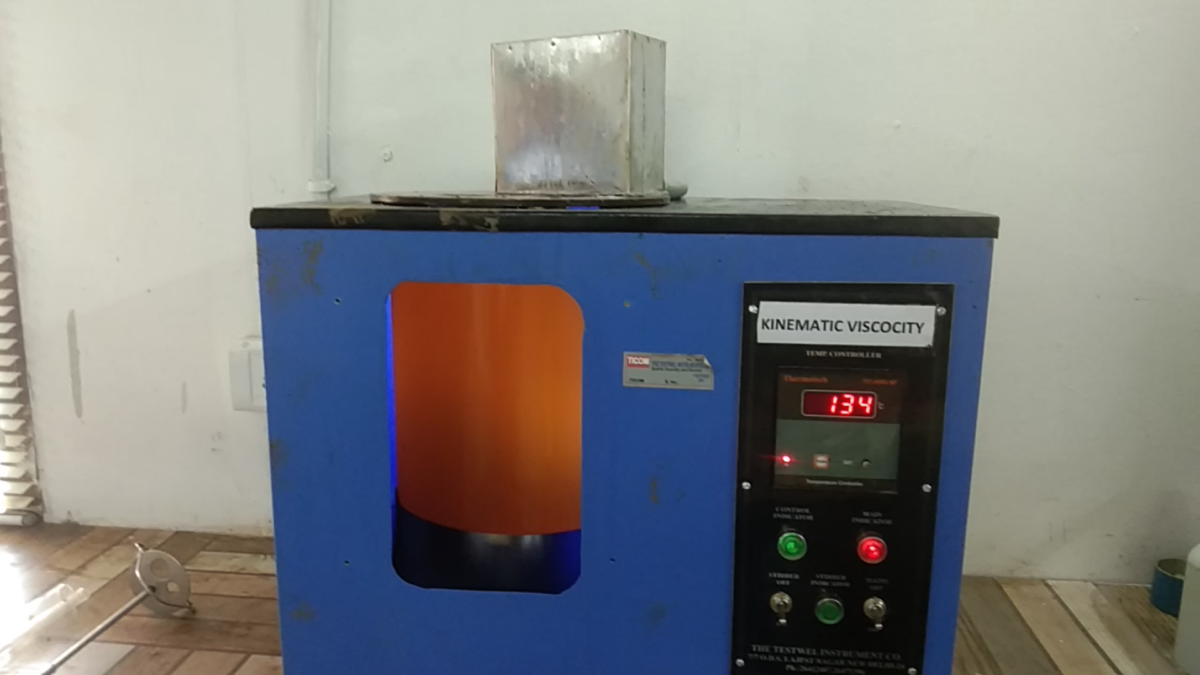
KINEMATIC VISCOSITY OF BITUMEN AS PER IS 1206 PART III

INTRODUCTION

The kinematic viscosity of a liquid is the absolute or dynamic viscosity (poise 60 ° C ) divided by the density of the liquid at the temperature of measurement. The 135° C (275° F) measurement temperature was chosen to simulate the mixing and lay down temperatures typically encountered in HMA pavement construction.The SI unit of kinematic viscosity is m2/s. The CGS unit of kinematic viscosity is the stokes (St).

SCOPE . IS 1206 (part III) covers the method for the determination of kinematic viscosity of paving grade and cut-back It is applicable to the materials having a viscosity range of 30-100000 cSt. Kinematic Viscosity of a Newtonian Liquid.
It may be defined as the quotient of the absolute or dynamic viscosity divided by the density of the liquid under test; both at the same temperature. The cgs unit of kinematic viscosity is the stoke which has the dimensions square centimetre per second. For petroleum products the kinematic viscosity is generally expressed in centistokes (cSt) which is 1/100 th of a stoke.

APPARATUS:

Bath :Suitable bath for immersion of the viscometer so that the liquid reservoir or top of the capillary whichever is uppermost is at least 20 mm below the upper hath level.

Timing Device – Any timing device such as stop-watch or stop clock capable of being read up to 0.5 s.

Procedure For Making Bitumen Sample

Heat the sample to a temperature not more than 90% for bitumen until it attains totally pouring consistency & stir it and transfer approximately 20 ml into a container. Precaution should be taken to avoid over-heating and having any entrapped air .

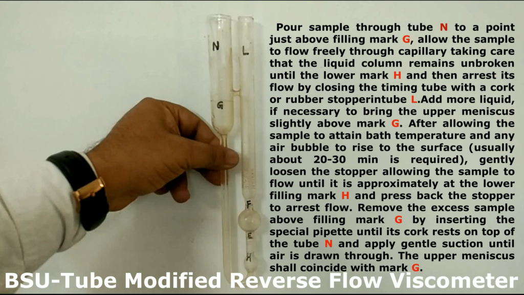
1.Mount the BS U-tube viscometer in the constant temperature bath keeping tube L vertical.

2.Pour sample through tube N to a point just above filling mark G, allow the sample to flow freely through capillary R, taking care that the liquid column remains unbroken until the lower mark H and then arrest its flow by closing the timing tube with a cork or rubber stoppering tube L

3. Add more liquid, if necessary to bring the upper meniscus slightly above mark G. and after allowing the sample to attain bath temperature and any air bubble to rise to the surface .

4.Gently loosen the stopper allowing the sample to flow until it is approximately at the lower filling mark H and press back the stopper to arrest flow.

5.Remove the excess sample above filling mark G by inserting the special pipette until its cork rests on top of the tube N and apply gentle suction until air is drawn through  the upper meniscus shall coincide with mark G.

6.Allow the viscometer to remain in the constant temperature bath for a sufficient time to ensure that the sample reaches temperature equilibrium. It takes about  30 min at 135°C.

7.After completion of 30 minutes ,remove the stopper in the tube N and L respectively and allow the sample to flow by gravity.

8.Measure to the nearest 0.1 s the time required for the leading edge of the meniscus to pass from timing mark E to timing mark F.

9. Note down the time .

CALCULATION Calculate the kinematic viscosity up to three significant figures With the help of following  equation: Kinematic viscosity cSt=Ct Where C = calibration constant of the viscometer in centistokes per second, and t = efflux time in seconds

Facebooktwitterredditpinterestlinkedinmail