Method statement for slurry seal

Slurry  is a combination or mixture of slow set bitumen emulsion , crusher dust with the addition of cement and water.
Application
It may be used to seal cracks,to provide a more even riding surface or a base for further treatment,before application, pothole and depression to be filled with proper bituminous material.

Material requirements

Aggregates:Suitable aggregate for slurry is graded crusher dust which is clean and free of any clay particles or organic materials.The crusher dust should comply with the specifications as stated in IS-383.A typical grading for suitable crusher dust is shown in the table below.Table 500-33 MORT&H

Sieve Size               % Passing

9.5                             100                                                
4.75                           90-100
2.36                           65-90
1.18                            45-70
0.600                       30-50
0.300                        18-30
0.150                         10-21
0.075                        5-15

Quantity of residual binder :Percentage by mass of aggregate should be 7.5 – 13.5

Water : Water shall be of such quality that the bitumen will not separate from the emulsion before the slurry seal is in place. The pH of the water must lie in the range 4 to 7.

Bitumen Emulsion : The emulsified bitumen shall be a Cationic rapid setting type as approved by the Engineer, conforming to the requirements as per IS: 8887.Slow setting bitumen emulsion is recommended .

Plant & Equipment Requirement :
Below is the list of plant required to mix and lay 5m3 or 700m² of slurry per day practically.

Item                                                           Number of items

Concrete mixer (0.3 m³)                                    1

Wheel barrows                                                       3

Shovels                                                                      5

Pick                                                                             1

Containers (25 litres)                                         5

Container (1 litre)                                                 1

Rubber squeegees                                                5

Hessian sheet (2m x 1.5m)                               1

Watering can                                                          1

Rope (10 mm diameter and 100m length) 1

Labour requirements

Below is the typical composition of a slurry team necessary to mix and lay 5m3 or 700m² per day.

Activity                                                            Number of workers

Loading of crusher dust                                      2

Concrete mixer operator                                     1

Pushing wheelbarrows                                       3

Loading emulsion and water                           2

Spreading with squeegees                                3

Sweeping                                                                  1

Traffic Control                                                       2

Construction

Site Preparation

Slurry should be applied during the day, only in fair weather conditions. Repairs to potholes and depression should have been done prior to resealing with slurry.The surface on which the slurry is to be applied must be thoroughly swept and free of any debris.The surface must be dampened slightly before the slurry is applied.

Mixing by hand

The mix proportions will vary depending on the source and grading of the crusher dust .Before laying the slurry , a trial mix test should be carried out in a small container.Can be adust with water The typical mix proportions are as follows:
Material                             By (Agg)% %              by mass(Overall)
Bitumen emulsion                13.5                                      10.5

Crusher dust                           100                                       77.5

Cement                                      1.5                                           1

Water                                          14                                          11

Total (dry)                              129                                       100

Remarks: % are shown with respect to crusher dust(100%) in 1st column and in 2nd column overall % has been given.

Work Sequences
The following mixing sequence is recommended to obtain a homogenous slurry mixture:
Step 1: Pre-wet the concrete mixer drum with approximately 5 litres of water
Step 2: Add the crusher dust into the concrete mixer
Step 3: Add the cement into the concrete mixer
Step 4: Mix the contents
Step 5: Pour water into the concrete mixer
Step 6: Mix again
Step 7: Pour in emulsion
Step 8: Mix contents
The emulsion must be at ambient temperature. To improve workability of the slurry, a controlled quantity of additional water should be added until the slurry has a creamy consistency . The water quantity will vary depending on the type of aggregate source its moisture content and prevailing air temperature.

Laying by hand
Slurry can be applied in a layer thickness of 4 mm-5mm.. A rope may be used to ensure straight edges and to control the cover thickness.
For instance to obtain a layer depth of 5 mm slurry, a 10mm diameter rope should be used.

After mixing, the slurry is transported in wheelbarrows to the point of application. The slurry is thenremixed on the road surface and spread with squeegees to obtain a uniform consistency and thickness.
The newly applied slurry layer is finished by dragging a wet hessian sheet over it to achieve a uniformly textured surface.If required rolling can be done with PTR depend upon condition

Traffic control

Slurry takes approximately four hours to set and dry properly under favourable weather conditions and no traffic should be allowed onto the freshly laid slurry before it has dried sufficiently. A suitable means of assessing this is to check whether the slurry can withstand the turning force of a shoe heel under a person’s weight without scuffing.

Quality control
Before construction commences the mix components should be mixed in their predetermined proportions in a small container to determine their compatibility. The resultant mix should be shaped into a patty and allowed to dry in the sun for a visual inspection.

The following tests should be carried out on site during the execution of the works:

  •  Daily: Bulking test on the crusher dust to determine whether the mix proportions require adjustment.
  • When the water source is changed, dilute the emulsion 50:50 with the water in a glass container to check whether the fluids are compatible.

The key variables that must be checked regularly are the grading of the crusher dust being supplied and the binder content of the final slurry mixture. To this end samples of the crusher dust and wet slurry mixture should be tested in a soils laboratory.

Facebooktwitterredditpinterestlinkedinmail

PROCEDURE OF LAYING DRY LEAN CONCRETE

DRY LEAN CONCRETE  is cement concrete with low slump as well as low cement which is being laid as a first layer for  rigid pavement over sub-base (GSB) , rolled & compacted by mechanical means.We will discuss with all sections one by one  as per following order:

  1. GENERAL
  2. REFERENCE
  3. EQUIPMENT WITH ESSENTIAL FEATURES
  4. MANPOWER REQUIREMENTS
  5. MATERIALS
  6. TRIAL STRETCH
  7. QUALITY CONTROL TESTING & ACCEPTANCE
  8. SAFETY REQUIREMENTS /MEASURES

1.GENERAL 

This work should be carried out accordance with the wants of Contract Specifications and in conformity with the lines, grades , drawings or as directed by the Engineer. The work will include furnishing of all plant and equipment, materials , labour and performing all operations, in reference to the work as approved by the Engineer.
The design parameters of dry lean concrete , if any will be as stipulated in the contract drawings.

2. REFERENCE

i) Clause 600 of MORT&H – 5th Edition
ii) IRC:SP: 49-2014
iii) IS: 16714-2018
iv) Relevant Approved Drawings

3. EQUIPMENT WITH ESSENTIAL FEATURES

i) Batching Plant
ii) Paver with Electronic Sensor
iii) Dump Trucks
iv) Water Tanker
v) 8-10 Tonne Roller
vi) Hand Tools: Shovels, Broom, Wire brush, Straight edge
vii) Testing Equipment’s: 20 cm dia Density cone, Vibrating Hammer, Cube Moulds, Thermometer.

4. MANPOWER REQUIREMENTS

i) Site Engineer
ii) Surveyor (With Team)
iii) Operators, Supervisors and Laying Team

5. MATERIALS

5.1 Source of Materials

Source the approval of material should be obtained from the Engineer at least 45 days before the scheduled commencement of the work. If later it is proposed to obtain the materials from a different source, Engineer will be notified for his approval at least 45 days before such materials are to be used.

5.2 Cement

Following sorts of cement could also be used with prior approval of the Engineer.
Ordinary Portland Cement 53 Grade IS:8112 Cement to be used may rather be obtained in bulk form. It will be stored in accordance with stipulations contained in Clause 1014.

5.3 Ground Granulated Blast Furnace Slag

GGBS should be used from approved source & complying the requirements of IRC SP: 49-2014

5.4 Aggregates

Aggregates for lean concrete will be crushed material complying with IS: 383. The aggregates will not be alkali reactive. The limits of deleterious materials will not exceed the requirements set out in IS: 383.

a)Coarse aggregate

Coarse aggregates will consist of clean, hard, strong, dense, non-porous and durable pieces of crushed stones or crushed gravel . The maximum size of the coarse aggregate will be 26.5 mm. The water absorption of coarse aggregate shall not exceed 3%.

b)Fine aggregate

The fine aggregate will consist of clean, natural sand or crushed stone sand or a combination of the two and will conform to IS: 383. Fine aggregate will be free from soft particles, clay, shale, loam, cemented particles, mica, organic and other foreign matter. The water absorption of coarse aggregate shall not exceed 3%.
The material after blending will conform to the grading as indicated in Table -1 of IRC SP 49-2014

5.5 WATER
Water used for mixing and curing of concrete will be clean and free from injurious amounts of oil, salt, acid, substance or other substances harmful to the finished concrete. It will meet the requirements stipulated in IS: 456.

5.6 Proportioning of Materials for the Mix

The mix will be proportioned with a maximum aggregate cement ratio of 14:1. The water content will be adjusted to the optimum as per Clause 4.2 of IRC SP 49 for facilitating compaction by rolling. The strength and density requirements of concrete will be determined in accordance with Clause 7.1 of IRC SP 49-2014 by making trial mixes.

5.7 Cement Content

The minimum cementitious   content in the lean concrete will not be less than 140 kg/cum. of concrete. If using GGBS minimum cement content shall not be less than 100 kg/m3.If this minimum cement content is not sufficient to produce concrete of the specified strength, it will be increased as necessary to obtained the strength.

5.8 Concrete strength

The average compressive strength of each consecutive group of 5 cubes made in accordance with IR: SP:49-2014 will not be less than 7 MPa at 7 days. In addition, the minimum compressive strength of any individual cube will not be less than  5.5 MPa at 7 days. The design mix complying with these requirements shall be worked out before start of work.

5.9 Sub-grade

The sub-grade will conform to the grades and cross sections shown on the drawings and will be uniformly compacted to the design strength in accordance with these specifications and specification stipulated in the contract. The lean concrete sub-base shall not be laid on a poor sub-grade , if any must be properly back-filled and compacted as per specification. As far as possible, the construction traffic will be avoided on the prepared sub-grade. A day before placing of the sub-base, the sub-grade surface will be given a light sprinkling  of water and rolled with one or two passes of a smooth wheeled roller after a lapse of 2-3 hours in order to stabilize loose surface and then check for compliance.

5.10 Construction

The pace and program of the lean concrete sub-base construction will be matching suitably with the program of construction of the cement concrete pavement over it. The sub base will be overlaid with cement concrete pavement only after 7 days after sub-base construction.

5.11 Batching and mixing

The batching plant will be capable of proportioning the materials by weight, each type of material being weighed separately. The cement from the bulk stock will be weighed separately from the aggregates. The capacity of batching and mixing plant should be at least 25 % higher than the proposed capacity for the laying arrangements & batching and mixing plant should have necessary automatic controls to ensure accurate proportioning and mixing. Other types of mixers will be got approved subject to demonstration of their satisfactory performance during the trial length.

6.0 Trial Stretch

A trial stretch shall be made to the required width and minimum of 60 metre length . The trial length shall contain construction of at least one transverse construction joint involving hardened concrete and sub-base to be laid subsequently, so as to demonstrate the soundness of the procedure. In one day not more than 30 m of trial stretch shall be laid. The in-situ density of the freshly laid concrete shall be determined by sand replacement method by making 3 density holes at equal distances that diagonally bisects the trial length, these shall not be made in the strip of 500 mm from the edges. The average of these shall be considered as 100%, and with this the field density of the regular work shall be compared. The hardened concrete may be cut for 3m width in the trial length and reversed to check the bottom surface for any segregation or honey-combing, if found necessary adjustments shall be made in the mix design.

6.1 Transportation and placing

The plant mix concrete shall be transported by sufficient number of trucks to ensure continuous, uniform supply of concrete to feed the laying Equipment. The mix shall be protected from the weather, by covering the tippers/dumpers with tarpaulin during the transit. The lean concrete shall be laid to the required widths, grades,camber and thickness with self-propelled, electronic sensor or mechanical paver.

The Equipment shall be capable of laying the materials in an even manner without segregation, to the specified thickness after the compaction. The paving machine should have facilities to give good initial compaction.

6.2 Compaction

The compaction shall commence as soon as the concrete laid and levelled to the full width till there is no further movement under the roller and the surface is closed. In addition to the number of passes required for compaction, there shall be a pass without vibration as preliminary pass and another at the end as final pass. The minimum dry density obtained shall be 97% of that achieved in trial length, and at a distance of 500 mm from edge it shall be 95% of that achieved in the trial length. The finished surface should be inspected immediately, and all loose, segregated or defective areas if any ,shall be corrected by using fresh lean concrete. Honeycombed areas, any level/ thickness deficiency and surface irregularities shall be corrected by concrete with 10 mm and down aggregates. Special care and attention shall be exercised during compaction near joints, kerb, channels, side forms, around gullies and manholes.

7.0 Quality Control Testing and Acceptance

  1. Curing

As soon as the lean concrete surface is completed, curing shall commence.

a) Curing shall be done by covering the surface by hessian cloth in two layers which shall be kept continuously moist for 7 days by sprinkling water.

b) If water-curing is not possible, the curing shall be done by spraying with liquid curing compound. The curing compound shall be white pigmented type with water retention index of minimum 90 percent, when tested in accordance with the test method given in Annexure-A of IRC SP 49 -2014 To check the efficiency of the curing compound, the supplier shall be required to provide the test certificate from a recognized laboratory. Curing compound shall be sprayed immediately after when rolling is complete & the surface shall also  be covered with wet hessian for three days.

2)Tolerance  

The tolerances for thickness shall be ± 10 mm.

3)Density

The dry density of the laid material shall be determined from density holes at locations equally spaced along a diagonal that bisects each 2000 sq.m or part thereof, of material laid each day. It shall not be less than 97% of design density .The control of strength shall be exercised by taking samples of dry lean concrete for making cubes at the rate of 3 samples for each 1000 sq.m or part thereof laid each day. The cube samples shall be compacted, cured and tested in accordance with IS: 51 6.

8.Safety Requirements/Measures

DLC laying team will wear personal protective equipment while producing, transporting and laying the mix. All safety measures will be taken as per approved plan.


Facebooktwitterredditpinterestlinkedinmail

GIRDER LAUNCHING

Transportation, unloading and erection of the precast prestressed concrete girders shall be done under the direction of  experienced  engineer  he should be present for all stages of girder loading, unloading and erection. We have divided all these process into 7 sections

1.OBJECTIVE:

This methodology describes a detailed procedure for the erection of PSC Girders. Minor changes to the methodology would be adopted to suit the site conditions.

2.SCOPE OF WORK:

The scope of this methodology covers Lifting, Transportation and Erection of PSC Girders for all Flyovers & Bridges.

3.RESPONSIBILITY:

The responsibilities of the entire operation shall be assigned to a Senior Officer of the company who shall take care as an In-charge regarding all

4.MANPOWER: 

  1. A) Personnel to be deployed for smooth conducting work
  2. Section In charge-01 No’s
  3. Site Engineer/Site Supervisor-01 No’s
  4. Fore Man-01 No’s
  5. Segment man-02 No’s
  6. Rigman-04 No’s
  7. Kalasi-06 No’s
  8. Crane Operator-2 No’s
  9. Hydra Operator-2 No’s
  10. B) Personnel to be deployed for safety during work 
  1. Officer Safety-01 No’s
  2. Supervisor Safety-01 No’s
  3. Marshal Man -02 No’s

5. MACHINERIES :

  1.  Modular Trailers with capacity of 60 MT (2 Nos.).
  2. Tyre mounted 180 MT crane with Telescopic or Lattice Boom (2 Nos.)
  3. Tyre mounted mobile 80 MT service crane (1 Nos.)
  4. Pilot van (1 No.)

6.0 CONSTRUCTION METHODOLOGY

6.1     PREPARATION OF SITE AT ERECTION POINT:-

Following points to be ensured:-

  1. The site of erection and the approach to be leveled, dressed and rolled (if required) so that the machineries viz; cranes and trailers move and can be placed on s firm ground in correct position.
  2. Overhead obstruction (if any) to be removed.
  3. Adequate Area lighting to be provided for work at night.
  4. Proper and safe access to be arranged for supervisory staff to climb up to the top of Pier Cap to check correct alignment/ level of girder when erected.
  5. All lifting tackles viz; Slings, D- Shackle, U clamp ropes and temporary packing viz. wooden block etc. to be checked regarding the Quality/ Soundness and kept near site.

6.2     LOADING OF GIRDER AT CASTING YARD:-

Following points to be ensured:-

  1. The girders are to be loaded at the casting yard either by the help of Mobile Cranes.
  2. The site where the girders are to be loaded on to the trailer to be dressed leveled and rolled (if required) for smooth and safe movement of trailers and cranes.
  3. After girder is loaded on to the trailers, the same is to be securely tied at two ends (near support) so that the same doesn’t tilt during transportation.
  4. Girders to be loaded for erection are to be identified and checked carefully regarding length etc. so that there is no mistake regarding the sequence to erection.
  5. The engineer shall check the identification mark, length and finishing of girders before loading on to trailers.
  6. Lifting tackles viz; slings etc. to be checked and sleepers/ packing are to be kept in correct position before placing the girders on to the trailer.

6.3     ERECTION OF GIRDER:-

  1. Before starting erection work the positions of trailer and the cranes are to be ascertained carefully to ensure that during lifting, swinging and placing on to the pier cap is done smoothly.
  2. Before lifting the girders, the Radius and Angle of the crane booms to be checked to ascertain safe lifting capacity during erection.
  3. The outriggers of the cranes must have proper supports/ packing so that during lifting, swinging and placing the girder, cranes remain stable.
  4. Once the girder gets lifted from the trailer, it is to be moved out from the erection site so as to provide adequate space during erection.
  5. The girders thus being erected to be placed directly on the Neoprene Bearing (which are to be fixed prior to erection in correct position and level). In-case the girder cannot be placed directly on the bearing the same is to be placed on Pier Cap on wooden sleepers and shifted to correct location by changing the position of the cranes.
  6. Before removing the slings from the erected girders it is important to temporarily support the girders by the help of proper diagonal supports. When the second girder is erected in position immediate arrangement is to be made to tie two girders at the support and at the middle by proper tie member (i.e. Channels, Angles etc.).
  7. The position of the cranes is to be changed for erection at each girder suitably as required.
  8. Once all girders for one carriageway are lifted and placed in positions, cross diaphragm are to be cast so that temporary ties can be removed.

 7.0     SAFETY:

Safety during lifting, loading, transportation and erection is the most important and primary consideration of the entire operation. The following points need to be checked and ensured:-

  1. Capacity of cranes, trailers, lifting devices and packing (wooden blocks) to be ascertained before use.
  2. The approach for the cranes and trailers both at the loading and erection point must be leveled, dressed and rolled to ensure smooth and safe movement.
  3. During transportation/ movement of cranes all care to be taken to ensure smooth traffic flow on the highway.
  4. A Pilot van with flag/ batten light must escort the cranes and trailers during their movement.
  5. Safety officer along with traffic marshals must be available during the entire operation to ensure safety.
  6. All persons engaged must use P.P.Es viz. helmets, belts, gloves, shoes, jackets etc.

Facebooktwitterredditpinterestlinkedinmail

METHODOLOGY FOR PRESTRESSING

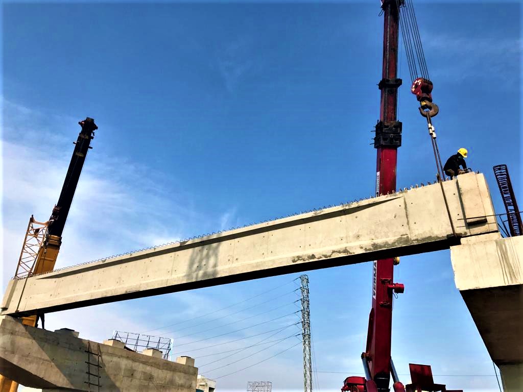
The technique of precasting is eminently suited to  bridge girder for quicker construction and minimum interference to traffic below the bridge. The girder my be cast in a central plant or in a temporary yard established near the work site. Girder upto about 40 meter can be precast in a single piece transported to site by means of truck cranes.In this article we will discuss pertaining to stressing and prestressing of girder methodology.

REFERENCE DOCUMENTS/CODES/DRAWINGS

1.MORT&H 5th Revision
2. IS: 14268 Stress Relieved Low Relaxation 7 Ply Strands for Prestressed Concrete.
3. IS: 210 Grey Iron Casting – specification
4. BS: 970 Specifications for Wrought Steels for Mechanical & Allied Engineering Purposes.
5. IRC: 18-2000 Design Criteria of Prestressed Concrete Road Bridges (Post-tensioned Concrete)
6. Relevant Prestressing Drawings (Latest Revisions)
7. Specifications Related to Prestressing Work

PRESTRESSING MATERIALS

• High Tensile Strands
Following are the properties of 12.7 mm Ø Low Relaxation High Tensile Strands. Oiled strand shall be used –

Nominal Area of Strand – 98.7 mm 2
Minimum Breaking Strength – 183.7 KN
Nominal Weight of Strand – 0.775 kg/mtr.

• SHEATHING PIPES

We are giving typical sheathing pipe , use pipe as per your project specification
84 mm ID & 98 mm OD & 2 mm thick HDPE sheathing pipes for 19 DP13
75 mm ID & 90 mm OD & 2 mm thick HDPE sheathing pipes for 12 DP13
51 mm ID & 64 mm OD & 2 mm thick HDPE sheathing pipes for 7 DP13
Sheathing duct shall be made up of HDPE of thickness (2.3 mm ± 0.3) mm with following properties –

• Approved 19 DP 13,12 DP 13 & 7 DP 13 Live end Anchorage System(Use Project approved brand)

The precast segment will be cast in casting yard. After curing is over, the segment will be shifted to the respective position and will be assembled with the help of launching girder. The high strength epoxy will be used for gluing two segment together and it will be stressed by high tensioned bar. After final stressing, temporary stress will be released

Tube Unit (Anchor Cone)

The basic raw material for manufacture of tube unit is gray cast iron. It allows the transfer of prestressing force from the bearing plate to the concrete. The Tube Unit is embedded in concrete and can be easily fixed to the MS cone box by means of bolts and nuts. The design of Tube Unit allows uniform flaring of H. T. Strands while stressing and free access to the injection of grout.
Anchor Head (Bearing Plate)

The basic raw material for manufacture of bearing plate is Steel casting / forged steel. The conical holes facilitate the seating of wedges and holding the strands in stressed condition.

Wedges
The basic raw material for manufacture of wedges is alloy steel. The individual high tensile strands passing through the bearing plate is anchored by the wedges. The 3 segments of the wedges are held together around the strand by means of special wire circlips for better functioning, easy placement and storage

Prestressing and Grouting is broadly divided into following activities, viz.,

1. Layout & Profiling of the cables/sheathing.

2. Fixing of tube unit/end block.

3.Concreting

4. Cable cutting and threading.

5.Fixing of Bearing plate & Wedges.

6. Stressing.

7. Cutting and end Sealing.

7. Grouting.

1. LAYOUT & PROFILING OF SHEATHING PIPES

After completion of alignment of bottom shuttering & bottom reinforcement of girder, layout & Profiling of cables shall be carried out in following steps :

• Layout of cables is carried out as per given ordinates & related reference drawings.
• After all ordinates are plotted, tie bars of 10 mm. dia. shall be installed as per ordinates to place the sheathing pipe wherever required. Installation of sheathing pipe is carried out over the tie rods.
• Sheathing pipe shall be supported in the bottom by tie rods & shall be cross bound using double binding wire. It should be ensured that the sheathing pipes are fixed firmly in position so as to prevent displacement during concreting by weight of concrete, vibration or by floatation.
• Connect the sheathing with the help of couplers provided at the end of each pipe.
• Sealing of sheathing joints will be done using PVC tapes. It will be ensured that no joints are remaining unsealed.
• Cable profile shall be checked. Vertical ordinates shall be check from soffit of the bottom shutters. Horizontal ordinates shall be check from the face of the side shutters, which has been already checked for verticality or as in drawing.

2. FIXING OF TUBE UNIT

• Fixing of tube unit shall be carried out after installation of end shuttering plate.
• Fix tube unit to End plate with the help of 4 nos. of bolts.
• Bursting reinforcement shall be fixed according to the drawing.
• Connecting the tube unit to sheathing pipe.
• Joint shall be sealed with the help of PVC tape.
• The face of the tube unit shall be truly perpendicular to the axis of the cable and about 1.5 m of cable before trumpet should be in straight alignment.
• After the fixing of tube unit and cable layout, insert the HDPE pipes Or HTS Strand inside all ducts to avoid the damage of sheathing pipe & ingress of cement slurry inside the duct at the time of concreting.

3. CONCRETING

• Although concreting is not a part of stressing but it has very important role in successful completion of stressing of structure.
• It shall be noted that the needle vibrator is not placed directly on sheathing pipe, which may damage the sheathing pipe.
• HDPE pipe Or HTS Strands in all the cables should be moved in both directions during the period of concreting.
• More attention should be given while concreting in the end block portion. Adequate compaction of concrete to be ensured to avoid any kind honeycombing.

4. CABLE CUTTING & THREADING

After completion of concreting & removing end block shuttering, cable threading shall be done.
• H. T. Strands shall be threaded manually.
• For cutting strands, a portable grinding wheel shall be used.
• H. T. Strands shall be cut as given in drawings, considering site conditions & gripping length of jack.

5. FIXING OF BEARING PLATES & WEDGES

• Fixing of bearings plates & wedges is done before stressing. It is ensured that the tapered holes in bearing plates & wedges are free of rust.
• Insert the strands into the tapered holes provided in the bearing plate.
• Install the wedges over the strands and push them with a pipe into the tapered holes of the bearing plate.
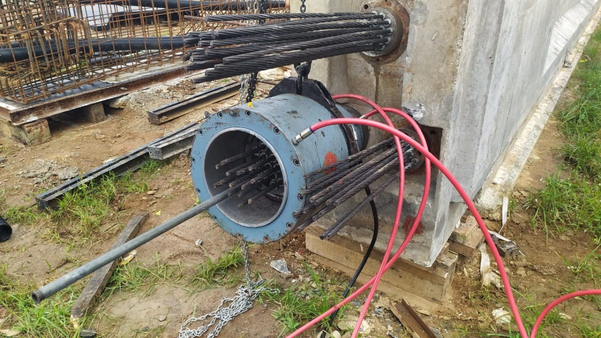
6. STRESSING

Prestressing of the girder is done as required by the system of prestressing and design. Following points will be observed while carrying out the stressing operation.
Only trained and experienced personnel, under the guidance of  technical Staff, should perform stressing & grouting.
• The required strength of the girder concrete as mentioned in drawings/specifications shall be ensured by cube testing before starting the stressing work.
• Stressing of cables shall be done as per the sequence mentioned in the drawings/specifications.
• The first stage stressing shall be done after the concrete achieves 35 Mpa strength or 10 days after casting, whichever is earlier. In the first stage two cables shall be stressed viz. cable no. 1 & cable no.2  or as shown in the drawing.
• In the second stage stressing balance two cables i.e. cable no. 3 & cable no. 4 shall be stressed after the concrete achieves 45 Mpa strength (28 Days strength ) or 21 days after the casting, whichever is later
• Elongation mentioned in the drawings must be modified for actual value of modulus of elasticity ‘E’ and the area of c/s of strands ‘A’ of the cables as per the results unless otherwise mentioned in the drawings/specifications.
• Actual pressure shall be calculated after applying Jack efficiency factor.
• Stressing shall be done using Multi-pull jacks only.
• Stressing shall be done from both ends, care will be taken to achieve almost equal readings of elongation at both the ends in each step of increment of pressure.
• Readings will be taken preferably at incremental steps of 50 kg/cm2 up to the final pressure.
• After locking the wedges the pressure in the jack will be released very slowly to avoid transfer of prestressing force by impact.
• In every cable instantaneous slip of anchorages must be recorded. It will be within limits prescribed by the designer or by the prestressing agency.
• The pressure applied and elongation achieved will match within the prescribed limits. Normally, the limit is 5% of pressure and elongations.
• No person will be allowed to stand behind the anchorages in any circumstances during the process of tensioning.

6.1 THE FOLLOWING STEPS SHOULD BE PREFERRED FOR JACK MOUNTING 

  • Fix the bearing plates at both the ends of the tensions.
  • Insert the bearing collar & fix it on tube unit with the help of screws.
  • Insert the lock-off plate as per the orientation the bearing plate.
  • A rigid runaway beam (ISMC/ISMB) structure shall be made at the end of the bridge girder from where the Jack is to be suspended by means of a chain pulley block. The arrangement will give full flexibility of movement of Jack both transversely and longitudinally.
  • Push the Jack over the strands. The axis of the Jack must coincide with the tendon axis. Insert the strand in to the Jack.
  • Apply “wax” inside the holes of pulling plate as well as outside of master grip.
  • Install the 3-piece wedge (master grip) over the strand into the pulling plate inside the rear of the Jack. Push the grips with a piece of hollow hammering pipe to seat tightly inside the pulling plate holes.
  • Ensure all connection of Jack with pump is correct and flexibility of hose pipe for movement of the Jack at the time of stressing.
  • It is important that the supporting chain or hook shall be slackened off as soon as the Jack starts to carry load, but they must be ready to support the Jack again when the pressure is released.
  • Locking pressure should be maintained approximately 70-80 % of the stressing pressure.

7.0 CUTTING AND END SEALING

Cutting should be carried out after checking the 24 hrs. slip loss. Strand should be cut approximately 40 mm. from the face of bearing plate. End sealing should be done with the help of GROUT CAP or Epoxy & cement  Mortar (Mounting the ends) .

7.1 GROUT CAP :

 The advantages of using Dynamic Grout Cap are used for speedy grouting and saving of sealing material i.e. cement mortar.

 7.2 FIXING OF GROUT CAP

  • The stressed strands are cut to the required length i.e. 40 mm. from the face of bearing plate.
  • On the inner surface of cap, grease should be applied.
  • ‘O’ ring should be placed in the slot provided along the periphery of the cap, which maintains the pressure and prevents the leakage of grout.
  • Grout cap is fixed by 4 nos. of allen key bolts by keeping the air vent nut in top position.
  1. GROUTING

Neat cement slurry should be filled in the annular spaces between sheathing duct & high tensile (H.T.) steel/strands.

8.1 OBJECTIVES OF GROUTING :

1.To protect the steel against corrosion.

2.Effective bond between the Prestressing steel and concrete.

8.2 MATERIALS FOR GROUTING :

(A) CEMENT:

Ordinary Portland cement should be used for the preparation of the grout. I. The cement shall have no false setting phenomenon and shall be at a temperature less than 40 °C at the time of production of grout. The cement should be free from chemical impurities like chloride and sulphate, which leads to corrosion of steel.

(B) WATER:

Clean potable water, free from impurities shall be used. Sea or Creek water shall be strictly avoided.

(C) ADMIXTURE :

While designing grout mix , we are using Sika (Intraplast N 200) 0.4 % by weight of cement). to reduce shrinkage of grout.

 8.3 WATER – CEMENT RATIO

Choose Water-cement ratio as low as possible , consistent with workability. This ratio should not normally exceed 0.45. We are keeping 0.39 as per site condition.(Can select W/C ratio as per your convenient)

8.4 GROUT TEMPERATURE

Generally, the temperature of the grout must be 25 °C. It is likely to change depending upon the site conditions. When the ambient temperature during the day is likely to exceed 40 °C, grouting shall be done in the early morning or late evening hours.

 8.5  TESTS ON GROUT MIX

The characteristics of the grout are determined on the grout itself or on samples made from the grout in accordance with the following.

  • Fluidity
  • Bleeding
  • Volume Change

8.6 GROUTING PROCESS

 Following points will be observed while doing the grouting.

  • Grouting of cables shall be done as early as possible, after completion of stressing.
  • All cables that are to be grouted shall be cleaned thoroughly with water & compressed air.
  • The grout mix is prepared in the agitator by thoroughly mixing it for 1 min.
  • The agitator must be placed at a height such that mortar can flow directly in top second tank placed beneath the outlet of agitator.
  • Before flowing in to the second tank mortar must be passed through a 2 mm. mesh screen so as to eliminate impurities and lumps which otherwise cause choking of the pump at the time of grouting process.
  • Connect the suction hose of grout pump to the second drum.
  • Operate the pump to drain off water from the pump and hoses.
  • Allow discharge of a small quantity of grout from delivery hoses to check the correct functioning of pump.
  • Connect the delivery hoses to the tube unit’s grout inlet opening and begin grouting.
  • Ensure that there is always enough grout in tank so that air is not sucked in to the pump.
  • When the grout flows out of the dead end tube unit’s grout opening, open the air vent nut of the grout caps of both the ends.
  • Block the outlet of the other end after being assured that the air has been completely bleeded and the duct is filled with grout.
  • Close the air vent nut and operate the pump until the desired pressure is achieved.
  • After the design pressure is achieved, stop the pump and maintain the pressure of 3-5 Kg/cm2 for 1 min. and close the valve of inlet connector.
  • Release the pressure in hose. The pump runs idle and returns grout to the tank.
  • Clean the grout pump & agitator with clean water to z avoid clogging.

  8.7 END PROTECTION OF ANCHORAGES

 Tendons shall be protected against corrosion by a plug at each end  to prevent passage of air. After grouting is over the anchorages will be  protected for corrosion as under –

  1. Clean the exposed anchorage parts for rust and dirt with wire brush manually.
  2. Clean the surface with cotton waste & apply a coat tar epoxy (solvent free araldite)

9   SAFETY PRECAUTIONS

 9.1  Safety Precautions While Concreting

Although concreting is not a part of prestressing, it plays a vital role in successful stressing of structure. Following points should be considered while concreting

  • Main contractor should ensure that vibration is to be supervised. It should be noted that needle is not directly placed on sheathing pipe, which may damage the duct & thereby blocking the path of strands.
  • The portion of the end block of the girder should be properly concreted. Weak concrete leads to puncture of tube unit & hence stressing should be done only if concrete is capable of taking the load.
  • It should be ensured that the bursting reinforcement in the end block zone is adequately & properly installed.

9.2  Safety Precautions While Stressing

Very large forces are introduced into the tendons during stressing and the equipment is under high hydraulic pressure. Hence, careful working can avoid accidents.

  • Only trained and experienced personnel, under the guidance of Dynamic technical Staff, should perform stressing.
  • The equipment, especially the high pressure hoses and the adaptors must be in perfect condition. Damaged hoses must be replaced immediately.
  • Jack should never be handled by hoses.
  • Stressing should be done according to specified data. The allowed maximum pressure should never be exceeded.
  • During stressing, nobody should be allowed behind or underneath the jack, since failure of a strand can cause fatal accidents.
  • For stressing close to traffic areas, the jack must be secured by ropes or chain hoist.
  • All bars, wires and strands should be stored carefully. Ensure that they are not damaged in any way and should be checked for rust and corrosion before they are used.
  • Care should be taken while handling coils of high tensile steel strand as they may ‘whip back’ with force, if not securely bound.
  • Hogging of the girder during stressing operation should be observed & recorded.

9.3  Safety Precautions While Grouting

  • Protective glasses must be worn during grouting operation.
  • Do not start the pump while valves are closed, it may cause damage to the pressure gauge.
  • Place the grout tank preferably at the same level of grout pump.
  • In case of a longer stoppage (more than 5 min), ensure that the grout does not get set in the pump, if necessary empty the grout and flush the pump with water.


Facebooktwitterredditpinterestlinkedinmail

METHOD OF TEST FOR MEASUREMENT OF SPREAD OF BINDER FOR PRIME COAT & TACK COAT

The layer between Bituminous Course and Crushed Aggregate Base Course (WBM & WMM) is called Prime Coat. Its purpose is to bind the loose aggregates of (WBM & WMM) so that it can be prepared for subsequent construction activity of laying bituminous layer.

The thin layer between two bituminous course is called Tack Coat. The purpose of Tack Coat is to form a bond between two bituminous layer. There is certain specification mentioned in any project for rate of application of Prime coat & Tack coat.

For measuring that application rate of Tack Coat & Prime Coat , we shall have a Aluminium or any other suitable light tray with dimension 200 mm(L) x 200 mm(B) x 20 mm(H) . A set of three plates are essential for this test.

Procedure :

1. Weigh all the three trays & numbered them.
2. Place these trays along the road in path at 10 metre interval between wheels of distributor.
3. Now pass the distributor .
4. After distributor crosses a length of 50 metre , remove the tray.
5. Immediately without losing time , weigh them to the first place of decimal.
6. Fill all readings into the format.
Take the average of them & compare with the specification. If more are less result is obtaining , adjust the speed of distributor .


Reference : IRC  2008

Format sample

Facebooktwitterredditpinterestlinkedinmail

METHOD STATEMENT OF THERMOPLASTIC


1.0 Scope

2.0 General

3.0 Materials

4.0 Procedure

5.0 Precaution

6.0  Opening to traffic

1.0 Scope

The work shall consist of providing and laying of pavement marking with hot applied thermoplastic paints (type-2) as per Clause 803 of MORT&H.

2.0 General

This method statement covers providing and laying of pavement marking with hot applied thermoplastic paints as Per IRC: 35 code of practice for road marking and specified in drawing of as directed by the Engineer.

3.0 Materials

Materials of road marking shall be hot applied thermoplastic compound and the same shall meet the requirements as specified in clause 803.2 of MORT&H.

Composition: The pigment, beads, and aggregate shall be uniformly dispersed in the resin. The material shall be free from all skins, dirt and foreign objects and shall comply with requirements indicated following table.

Proportions of constituents of Material (% by weight)

Note: Amount of calcium carbonate and inert fillers shall be at the option of the manufacturer, provided all other requirements of this specification are met.

3.1 Properties: The properties of thermoplastic material, when tested in accordance with ASTM D36/BS-3262-(Part I) shall be as below;

a. Luminance :

 b. White: Daylight luminance at 45 degrees – 65 percent min as per AASHTOM 249.

 c. Drying time:  when applied at a temperature specified by the manufacturer and to the required thickness, the material shall set to bear traffic in   not more than 15 minutes.

d. Skid resistance: not less than 45 as per BS 6044.

e. Cracking resistance at low temperature: The material shall show no cracks on application to concrete blocks.

f. Softening point: 102.5+/- 9.5ºC as per ASTM D 36.

g. Flow resistance: Not more than 25 per cent as per AASHTO M 249.

h. Yellowness index (for white thermoplastic paint: not more than 0.12 as per AASHTO M 249.

i. Storage life: The material shall meet the requirements of these specifications for a period of one year. The thermoplastic material must also melt uniformly with no evidence of skins or un-melted particles for the one year storage period. Any material not meeting the above requirements shall be replaced by the manufacture/supplier/Contractor.

j. Reflectorisation  : shall be achieved by incorporation of beads, the grading and other properties of the beads shall be as specified in clause 803.4.3 of MSRT&H.    

3.2 Marking: each container of the thermoplastic material shall be clearly and indelibly marked with following information.

The name, trade mark or other means of identification of manufacturer.

Batch number

Date of manufacture.

Colour (white or yellow)

Maximum application temperature and maximum safe heating temperature.

3.3 Sampling and Testing: The thermoplastic material shall be sampled and tested in accordance with the appropriate ASTM/BS method. The Contractor shall furnish to the Employer a copy of certified test reports from the manufacturer of the thermoplastic material showing results of all tests specified herein and shall certify that  the material meets all requirements of this specification

3.3.1 Reflective glass beads

The glass beads shall be transparent, Colourless and free from milkiness, dark particles and excessive air inclusions. These shall conform to the requirements spelt out in Clause 803.4.2.3 of MORT&H.

Gradation: The glass beads shall meet the graduation requirements for the two types as given in the following table Table 800-10

Roundness: The glass beads shall have a minimum of 70 per cent true spheres

Refractive index: The glass beads shall have a minimum refractive index of 1.50.

Free flowing properties: The glass beads shall be free of hard lumps and clusters and shall dispense readily under any condition suitable for paint stripping. They shall pass the free – Flow test.

Before taking up of laying markings, program for the diversion of traffic shall be drawn up and got it approved by the Engineers as per 112 of MOSRT&H and as per IRC: SP-55.

Temporary sign boards, barricading, flags, lights and flagmen will be provided at working area as per approval of the Engineer.

On both sides, suitable regulatory/warning signs as approved by the Engineer shall be installed for the guidance or roads users.

4.0  Procedure

4.1  Equipment to be used

  1. Pre-Melter
  2. Pram-applicator
  3. Mechanical Broom
  4. Air compressor
  5. Truck
  6. Water tanker with pipe attachment
  7. Survey kit / instrument

4.2 Construction operation

4.2.1 Preparation (as per MORT&H Clause:803.4.4):

The material shall be melted in accordance with the manufacturer’s instructions in a heater fitted with a mechanical stirrer to give a smooth consistency to the thermoplastic material to avoid local overheating. The temperature of the mass shall be within the range specified by the manufacturer, and shall on no account be allowed to exceed the maximum temperature stated by the manufacturer. The molten material should be used as expeditiously as possible and for thermoplastic material which has natural binders or is otherwise sensitive to prolonged heating the material shall not be maintained in a molten condition for more than 4 hours.

After transfer to the laying equipment, the material shall be maintained within the temperature range specified by the manufacture for achieving the desired consistency for laying.

4.2.2 Cleaning: The surface of the flexible road pavement shall be thoroughly cleaned form all of dust any other material, grease, oil etc. at the area where the material shall be applied to mark the pavement with the help of broom and air compressor.

4.2.3 Pre- Marking: The reference centre – line ( Pre-Marking) of the lane marking as per the drawing shall be made to have temporary marking with chalk powder/long thin rope ,so that the applicator machine pointer in the front of the machine can be guided to move along this pre-Marked line while material is being applied on the road . This ensures accurate alignment of the markings when laid on the road surface.

4.2.4 Heating of the Material: The material shall be heated in the pre-Melter as well as pram-applicator machine fitted with mechanical stirrer to give smooth consistency to the material and to avoid local heating of the material. For heating, LPG with suitable burner system shall be used to achieve temperature of 180+/-10º C which is the specified application temperature. The temperature Gauge fitted on the machine as well as the pre-Melter displays the material temperatures continuously for monitoring the application temperature.

4.2.5 Lane Markings: The lane marking shall be made as per the approved drawing for width; length and thickness shall be made with the help of the Screed- Box attached to the Applicator Machine. The thermoplastic paint shall be applied in intermittent of continuous lines of uniform thickens of at least 2.5 mm. where arrows or letters are to be provided. Thermoplastic compound may be hand sprayed. The tolerances of the width, position alignment and length of segment of broken lines shall be as per Technical specification sub clause 803.6.6.

4.2.6 Drop-On Glass Beads Application: The approved glass beads shall be placed in position from the bead dispenser attached to the machine and the dispersion is by forced –feed mechanism which works while the machine is applying the markings with the screed –Box., simultaneously and before the thermo plastic material (which is hot applied) becomes dry and cold while achieving road surface temperature. The type-2 glass beads conforming to the above noted specification shall be sprayed uniformly into a mono-layer on to the paint line at the rate of 250 grams per square meter area.

5.Precaution:

1.The strip shall not be slippery when wet.

2 .The marking shall not lift from the pavement in freezing weather.

3.After application and proper drying, the stripe shall shown no appreciable deformation or discoloration under traffic and under road temperatures up to 60º C.

4.The marking shall not deteriorate by contact with sodium chloride or oil drippings from traffic.

5.The stripe or marking shall maintain its original dimension and position. Cold ductility of the material shall be such as to permit normal movement with surface without chopping or cracking.

6.The marking shall be done with approved Material ONLY on dry pavement surfaces of minimum Temperature of 10º C.

7.The arrow marking shall be made using the approved material with specifically made stencils of shape and size.

6.Opening to traffic: Traffic will be opened after 24 hours.


Facebooktwitterredditpinterestlinkedinmail

CONCRETE KERB CASTING METHOD STATEMENT

This Method Statement provides detail procedure for the laying of concrete Kerb as per the approved drawing.

  • Scope

This work consists of constructing cement concrete kerb in the central median and /or along the footpaths in conformity with the lines, levels and dimensions as specified in the drawings.

  • Responsibility

Section In charge will be responsible for quality control of the section for the construction of Kerb. Further field engineers, surveyors, supervisors and lab technicians will assist him.

  • Equipment

A continuous kerb casting equipment will be deployed capable of laying the kerb in required cross-sections and producing a well-compacted mass of concrete.

Where continuous casting with Equipment is not practicable, manual construction with suitable shutter will be done with the approval of the Engineer.

  • Procedure
  1. Lines and levels will be marked and the sensor of the kerb-casting machine will be adjusted accordingly. Pegs will be put at every 10 meters interval indicating the levels. These pegs will be joined with a metal wire.
  2. The concrete of Grade M20 to be used for kerb will be produced at the batching plant as per the approved mix formula.
  3. The concrete will be loaded on to the transit mixer directly from the batching plant and transported to the kerb location.
  4. Kerb casting will be laid on firm foundation of minimum 150 mm thickness of cement concrete of M10 grade cast-in-situ and extending 50mm beyond the kerb stone or over WMM surface as per site condition.
  5. Before laying the foundation with lean concrete, the base will be leveled and lightly watered to make it damp.
  6. The cast – in – situ kerb will be constructed in all situations except at location where continuous casting with Equipment is not practicable, manual construction with suitable shutter with the approval of the Engineer.
  7. In the median portions in the straight reaches, the kerb will be cast in continuous lengths. In the portions where footpaths are provided and /or the slope of the carriageway is towards median gap/recess will be provided in the kerb by cutting to facilitate drainage openings.
  8. After laying the kerbs and just prior to 6 to 8 hours after laying of the concrete, saw cut grooves will be provided at 5m intervals or as specified by the engineer.
  9. Curing of kerb will be done by applying curing compound / or any other suitable method
  10. Vertical and horizontal tolerances with respect to true line and level will be + 6mm.
  11. Saw joint groove mechanically cut to 3mm to 5mm wide.
  • Quality Control Testing and Acceptance

Quality control tests shall be done as per Quality Control Tests and Acceptance Criteria


Facebooktwitterredditpinterestlinkedinmail

METHODOLOGY FOR WET MIX MACADAM

Wet Mix Macadam consist of laying spreading and compacting of clean, crushed, well-graded granular materials on a prepared and approved Granular sub-Base. The material is well mixed with water and rolled to a dense mass. It shall be laid on one or more layers as per line and level, grade and cross section shown in the drawing or as directed by the Engineer. The thickness of single compacted Wet Mixed Macadam (WMM) Base shall not be less than 75 mm. Maximum thickness of single compacted layer base can be up to 250 mm upon approval of Engineer.

1. Reference

2. Setting Out.

3. Selection of Material.

4. Equipments.

5. Methods of Operation.

6. Quality Control.

7. Work Safety.

8. Environmental Safety.


1.0 Reference

Reference Documents:-
I) Ministry of Road Transport& Highways Specifications
II) Technical Specifications
III) Relevant Drawings.
IV) IS 2720 Codes.

2.0 Setting Out

After the layer of GSB Sub-Base has been approved, then line and level are carried out to fix the Wet Mix Macadam base layer (herein after called WMM Base). Pegs are fixed at regular intervals on the safe side of the road edge where blade of grader should not disturb the peg while blending of the Base materials. On each peg’s top level of Base layer is marked. The chainage boards and working bench mark shall be set out side the limits of construction areas.

3.0 Selection of Material

3.1 Aggregate

Coarse aggregate shall be crushed stone or crusher run as per IRC 109 or clause 406.2.1 of MORT&H specification.

3.2 Physical requirement

The constituents of the aggregates shall be produced by integrated crushing and screening plant (Impact or Cone type) and, unless otherwise instructed by the Engineer, crushing shall be carried out in at least two stages. The fraction of material passing through 4.75mm sieve shall also be crusher run screening only. The aggregate shall conform to the physical requirements set forth in Table 400-12 of MORT&H. or IRC 109 clause 3.1.1
If the water absorption value test of coarse aggregate is greater than 2 per cent, the soundness test shall be carried out on the materials delivered to site.
3.3 Grading Requirement

The aggregate shall conform to the grading given in table 406.2.1.2 of technical specification or IRC 109 -2015. Material finer than 425 micron, shall have Plasticity Index (PI) less than 6. The final gradation approved within these limits shall be well graded from coarse to fine and shall not vary from low limit on one sieve to high limit of adjacent sieve or vice versa.

4.0 Equipments

The following equipments shall be carried out for the WMM

1. Wet Mix Macadam Plant

2. Dumper / Tippers.

3. Vibro Roller (80 to 100 KN)

4. Water Tanker

5. Paver capable of paving more than 9 meter width.

6. Survey kit / instrument

5.0 Method of Operation

5.1 Preparation of WMM Base (As per clause 406.3.1):

5.1.a Provision of lateral confinement of aggregates

Proper arrangement shall be made for the lateral confinement of wet mix during laying. This shall be done by laying materials on adjoining shoulder along with that of WMM layer. The preparation of mix, spreading of mix and compaction are done sequentially.
The sequence of operation shall be followed as described in clause: 406.3.3 of MORT&H.

5.2 Preparation of mix

Wet mix Macadam shall be prepared in an approved WMM mixing plant having provision for controlled addition of water and forced/positive mixing arrangement. Optimum moisture for mixing shall be determined in accordance with IS: 2720 (Part 8) after replacing the aggregate fraction retained on 22.4 mm sieve with materials of passing from 22.4 and retained on 4.75 mm. While adding water, evaporation loss shall also be taken into account. The mixed material should be uniformly wet and no segregation shall be permitted.

5.3 Spreading of mix

Immediately after mixing, the aggregate shall be spread uniformly and evenly upon the approved GSB layer. Materials should neither be dumped in heap nor their hauling over a partly completed stretch. The first layer will be laid by motor grader and the second layer mix shall be spread by a WMM paver finisher capable of paving minimum 4.5m to 9.0m width. The layer may be tested by depth block during construction. No segregation of materials are allowed. The aggregates should be of uniform gradation with no pockets of fine materials.

5.4 Compaction

After the mix has been laid on site to the required thickness, grade and camber, then compaction is carried out with suitable roller to the full depth. For a thickness up to 200mm in a single layer, compaction shall be done with vibratory roller of 80 to 100 KN static weights with plain drum or equivalent capacity roller. Rolling is done from lower edge towards upper edge longitudinally for the portion having unidirectional cross fall and super elevation.
Each pass of the roller shall uniformly overlap not less than one third of the track made in the previous pass. During rolling, grade and cross fall shall be checked and any high spot or depressions, which become apparent, corrected by adding or removing fresh materials. The speed of roller shall not exceed 5km/h. Rolling shall be continued till the density of the layer is achieved 98% of the Maximum Dry Density.
Rolling should not be done when the WMM layer is soft or yielding or when it causes a wave like motion. If level difference or irregularities develop during rolling which exceeds 12 mm when tested with 3 metre straight edge, the surface should be loosened and premixed materials added or removed as required before rolling again. In no case the unmixed material be permitted to make up the depressions.

5.5 Opening to traffic

After testing the compaction & level of WMM course the road shall be allowed to dry for 24 hours. Preferably no vehicular traffic should be allowed on the finished WMM surface till it has dried and covered with wearing course.

6.0 Quality Control

Table 400-12 Physical Requirement of coarse aggregate for Wet Mix Macadam for Sub-base /Base Courses

 406 WET MIX MACADAM SUB BASE /BASE

     Table 400- 13: Grading Requirement of Aggregate for Wet Mix Macadam

  1. Control Tests for Granular WMM Base: Post Construction
  2. Tolerance in Surface Level                                             : +10 mm
  3. permissible undulation (with 3 m straight edge) : 8 mm
  4. no. of undulations permitted in any 300 m length, exceeding 12 mm: 20
  5. Control on quality of materials and works shall be in accordance to section 900 of MORT&H.

7.0     Work Safety

 1.Safety will be provided location specific safety plan.

8.0   Environmental Safety

1.Nearby Streams, water courses, lakes, reservoir shall be protected from contamination by the soil erosion from areas exposed during excavation by constructing temporary berms, dykes, sediment Basins, slopes, drains & by the use of temporary mulches, seeding or other control devices.

2.Vehicles tracks shall be kept moist to prevent flying of dust particles with the vehicle movement.


Facebooktwitterredditpinterestlinkedinmail

Method Statement of Longitudinal Drain

The Scope of this work covers the following activities:
The excavation necessary for construction of Longitudinal Drain as per Section 300 MORT&H Specifications.
The selection of various construction materials, testing of materials, approvals and quarry selection, testing and approval of various grades of materials etc. conforming to section 1000 MORT&H Specifications
The construction of Longitudinal Drain with reference to, Section 300, Section 1000, Section 1500, Section 1600 and Section 1700 of MORT&H Specifications.

1.0 Materials
2.0 Plant, Equipment and Machinery
3.0 Construction Operations
3.1 Survey and Setting Out Works
3.2 Shop Drawing submission
3.3 Construction of Longitudinal Drain
3.3.1 Excavation
3.3.2 Bedding for Longitudinal Drain
3.3.3 Construction of Longitudinal Drain Base slab (Raft) by Cast-in-Situ Method
3.3.4 Construction of Longitudinal Drain walls – Stage 2
3.3.5 Construction of Longitudinal Drain by Precast Drain Method
3.3.6 Spreading, Compaction and Testing for Backfilling Material on both sides of Longitudinal Drain Backfilling behind Structure
4.0 Work Safety
5.0 Records

1.0 Materials:

• Ordinary Portland 43 Grade conforming to IS 8112, or 53 Grade Cement conforming to IS 12269.
• Coarse Aggregates, Sand / Fine Aggregates as per IS 383 and the tests shall be carried out as per IS 2386.
• The formwork material shall comply with IRC 87.
• Reinforcement steel bar shall be Fe 500 grade and conforming to IS: 1786.
• Water conforming to section 1010 MORT&H Specifications

2.0 Plant, Equipment and Machinery:

The following plant and equipment are necessary for the planned progress: –
a) Batching Plant.
b) Transit Mixers.
c) Needle Vibrators.
d) Slump cone and concrete test cube moulds.
e) Concrete Pump and Crane bucket.
f) JCB/Excavator.
g) Tippers/Dumpers.
h) Steel Shutters as formwork.

3.0 Construction operations.

3.1 Survey & Setting out Works

The limits for excavations shall be set out true to lines, curves, slopes, grades and sections as shown on the drawings or as directed by the Engineer and using established Bench Marks / Co-ordinates. All the Survey Instruments used shall be calibrated periodically as per the Calibration Plan. Survey Check Reports and other relevant data shall be maintained in relevant inspection formats.

3.2 Drain drawing submission

The  drawing for the Longitudinal Drain shall be made with the Invert levels shown with the indication of type of bedding as specified on the working drawing.
Before any construction work is being carried out, the Contractor must submit an elevation of the Invert Level showing the length to be constructed and the following details to be incorporated on the shop drawing:-
• The existing ground profile.
• Founding levels at the base.
• Invert levels of Longitudinal drain from one point at downstream to upstream.
• The invert levels of the longitudinal drain intersecting the box culvert
• The Longitudinal drain bar bending schedule should be submitted together the shop drawing.
• The Engineer’s approval for the shop drawing and bar bending schedule should be obtained well in advance of the scheduled start date of the Longitudinal Drain.

3.3 Construction of Longitudinal Drain

3.3.1 Excavation

The foundation bed for the Longitudinal Drain shall be excavated true to the lines and grade as set out. It shall be executed to provide sufficient room for steel shutters.

3.3.2 Bedding for Longitudinal Drain

The bedding surface of filling area must be a firm ground of uniform density throughout the length of the drain. It shall be compacted and tested so that it is good for the PCC to be laid on it.
The bedding surface of cutting area shall be clean and free from loose materials. Then lay the PCC to required thickness and dimensions. The finished surface should be uniform in thickness.

3.3.3 Construction of Longitudinal Drain Base slab (Raft) by Cast-in-Situ Method

The base slab dimensions shall be marked on the PCC.
After the above step is satisfactorily completed, fix the base slab reinforcement which were cut and bend in conformity with the bar bending schedule. Concrete covers shall be uniformly spaced at the bottom to support the reinforcement.
Clean up any debris in the PCC by blowing out any foreign materials not permitted.
All temporary shuttering shall be checked so that they are securely fixed.
When the approval to go ahead with concreting is obtained from the Engineer, order the calculated quantity of concrete for the pour.
The concrete should be uniformly vibrated with a needle. Conduct the routine slump checks and make test cubes as directed by the Engineer.
25mm Expansion joint gap to be provided at every 40 m interval to be filled with Salutex board and filler material (water proof).
Upon completing the concreting it is essential to cure the concrete with potable water on the next day and regularly do so for the next 7 days.

3.3.4 Construction of Longitudinal Drain walls – Stage 2

1.Tie the wall reinforcement which were cut and bend as per the bar bending schedule. When the Contractor is satisfied that the preparation is ready for inspection, submit a request to the Engineer for reinforcement inspection by raising a RFI.

2.Fix the steel shutters forms for the walls for stage 2 concrete after obtaining approval from the Engineer on the wall reinforcement. The steel shutters must be properly fixed and fastened together. Attention must be given to external lateral bracings are sufficient and would prevent bulging of concrete. Check that all gaps between steel shutters are properly plugged to prevent leaking of concrete slurry during vibration of the concrete. Next, when the Contractor is satisfied that the preparation is ready for inspection, submit a request to the Engineer for inspection by raising a RFI.

3.The Engineer carries out his inspection and approval given to proceed. Order, pour and vibrate the concrete in an acceptable manner specified by MORT&H Specifications. The concrete should be uniformly vibrated with a needle. Conduct the routine slump check and make test cubes as directed by the Engineer.

4.Upon completing the concreting it is essential to cure the concrete with water the next day regularly and continuously for the next 7 days.

3.3.5 Construction of Longitudinal Drain by Precast Drain Method

1.The base of the drain shall be formed with sand compacted to the required gradient.The drain centre line shall be maintained with the use of a string tied to wooden pegs from the downstream end to the upstream end.

2.The precast drain already lined up along the edge of the trench shall then be lifted by a JCB, equip with two steel rope (or acceptable slings) for lifting, and put in place in the trench.

3.The string shall be the guide in installing the precast drain unit from downstream to upstream.

4.The joints between drains shall be sealed with cement/sand mortar.

5.The next step is to construct the upper part where the reinforcement has been left for overcoming variation in depth of the Longitudinal Drain. This portion of work shall be constructed by the cast-in-situ method described in 3.3.3.

3.3.6 Spreading, Compaction and Testing for Backfilling Material on both sides of Longitudinal Drain

1.Back filling behind the drain shall be carried out as per the Clause 305 in MORT&H.

2.Back fill materials from approved Borrow areas will be spread in Layers to get 150 mm compacted thicknesses for the required length and width.

3.The required Cross Slope and Gradient shall be maintained as per drawings.

4.In areas where using vibratory rollers is not possible to carry out the compaction, suitable means like mechanical tamper, rammer, plate vibrator etc. shall be used for the compaction.

5.The frequency of testing and the type of tests to be conducted on compacted Backfill behind structures shall be as per MORT&H Specifications.

4.Work Safety Plan

The construction area occupied by the longitudinal drain shall be cordoned off from other earth moving plant working in the vicinity with warning tape. The contractor’s site safety team must conduct regular checks to see that the safety put up is in working condition at all times.

If concrete pouring has to continue beyond daylight, proper lighting should be organized ahead and standby for use when necessary.

Safety will be provided as per location specific safety plan.

6.Records

All records should be carefully documented and kept on all items of works so that when making payment to the Contract it is in order.


Facebooktwitterredditpinterestlinkedinmail

METHOD STATEMENT FOR DENSE BITUMINOUS MACADAM (DBM)

This work shall consist of laying in a single course a 50 to 100 mm – thick layer of DBM on a previously primed and approved Wet Mix Macadam Layer, as per specified lines & grades and in accordance with clause 507 of MORT&H specification or project specification.

1. REFERENCE DOCUMENTS.

2. MATERIALS.

3. MIX DESIGN.

4. PLANTS & EQUIPMENTS.

5. CONSTRUCTION OPERATIONS.

6. ARRANGEMENT FOR TRAFFIC.

7. QUALITY CONTROL

1. REFERENCE

Reference Documents:-
1. Ministry of Road Transport & Highway Specifications.
2. Technical Specifications
3. Relevant Drawings.

2. MATERIALS

The source and test report of all material will be submitted to the Engineer for approval before using the material as per clause 505.2 of MORT&H.

2.1 Bitumen

Bitumen shall be Viscosity grade or as per specified in the contract .

2.2 Coarse Aggregates

Coarse aggregate shall be obtained from the approved quarry. One cone crusher shall be installed at the quarry site. This crusher shall produce aggregates cubical / angular type so that flakiness and elongation indices are contained within the specified limit. The coarse aggregate shall satisfy specification as per Table 500-8

2.3 Fine Aggregate

Fine aggregates shall be of the fraction passing 2.36 mm sieve and retained on 75 micron sieve, consisting of crusher run screening, sand or a mixture of both. Natural sand is not allowed as a fine aggregate in bituminous mix.

2.4 Filler
Filler shall consisting of crusher dust, hydrated lime, or cement and shall satisfy the grading limit set in Table 500-9.The PI should not be more than 4.However, It is not applicable in case , if filler is Lime or Cement.
Where aggregate fails to comply the water sensitivity test then 2% by weight of aggregate lime or cement is required.

3. MIX DESIGN

3.1 Requirement of Mix

Apart from conformity with grading and quality requirements of individual ingredients, the mix shall meet the requirements set out in Table-500-11, MORT&H specifications. .Job mix formula shall be submitted 21 days in advance when going to start the bituminous work.

3.2 Binder Content

The binder content shall be determined to achieve the requirements set out in Table-500-10, MORT&H specifications and traffic volume specified in the contract. The Marshal method for determining the optimum binder content shall be adopted as described in the Asphalt Institute Manual MS-2.If the specific gravity of aggregate is more than 2.7 ◦C The minimum bitumen content can be reduced subsequently. Where the maximum size of aggregate is more than 26.5 mm , the modified marshal test by using 150 mm diameter mould as specified in MS-2 and ASTM D 5581 shall be used. When the modified procedure is used. The minimum stability should be multiplied by 2.25 and minimum flow should not be less than 3mm.

3.3 JOB MIX FORMULA

Job mix formula should be as per clause. 505.3.3 The .Job Mix formula should be true representative of material used and satisfy all the criteria set forth in Table 500-10 & 500-11.

3.4 Plant Trials

After the job mix formula approved plant trial should be done to confirm the bituminous mix design. The formula should be within limit as per set forth in Table 500-13 and shall satisfy the quality control criteria as per section 900. or project specification

4. PLANTS & EQUIPMENTS

1. Crusher of required capacity
2. Hot Mix Plant
3. Paver with sensor arrangement and capable of paving 9 meter width of mat.
4. Steel Tandem Rollers with required weight
5. Pneumatic Roller with required weight
6. Bitumen Sprayer
7. Dumpers
8. Air compressor
9. Pegs for putting levels
10. Mechanical broom
11. Straight edge
12. Camber plate
13. Thermometer
14. Gauge for checking thickness
15. Survey Kit / instrument.

5. CONSTRUCTION OPERATIONS

5.1 Weather and Seasonal Limitations

The work of laying shall not be taken up during rainy or foggy weather/ the base course is damp or wet or during dust storm or when the atmospheric temperature in shade is 10 deg. or less as specified in clause 504.3.1 0f the MORT&H specifications.

5.2 Preparation of Base

The WMM surface already prepared to the specified lines, grades and cross sections shall be swept clean free from dust and foreign matters using mechanical broom or blown off by compressed air as specified in the MORT&H specifications.

5.3 Tack Coat
The binder for tack coat shall be RS-I Grade Emulsion and shall be applied as per clause 503 of the MORT&H specifications.

5.4 Preparation and Transportation of Mix
DBM should be produced on batch basis by weight in Hot Mix Plant. The mixing will be done in a twin shaft pug-mill, which will produce a homogeneous mix.
The mixture shall be transported from the batching plant in tippers covered with tarpaulin (if required) so as to maintain the temperature and dust.

5.5 Spreading

The mix shall be transported to the site by the dumpers, which shall slowly discharge the mix in the paver hopper, while both the tipper and paver will move forward steadily and slowly. The automatic sensor shall ensure that the mix is being laid to the proper line and grade and level. The direction of the paver will be guided by the string lines fixed with the stack
& arms on both sides of the edges 0.5 m away from the edge. The paving will be done in one go for the full width of 9 meter. The minimum temperature of the mix at the time of laying shall be VG30/VG40——- 140°C/160 °C .
Transverse joints shall be cut vertically with asphalt cutter and a coat of hot bitumen shall be applied before placing materials.

5.6 Compaction

As soon as the mix has been laid to the paver, compaction shall be done with the help of a set of rollers moving at a speed not exceeding 5 km/hour following close to the paver. Rolling sequence will be as under or as established during laying trial stretch.
Compaction subsequently completed before the temperature falls below the minimum rolling temperatures VG30/VG40——90°C/100 °C.
Longitudinal joints shall be rolled immediately behind the paving operation. After this, rolling shall commence at the edges and progress towards the centre longitudinally except that on super elevated and unidirectional cambered portions, it should be started from the lower edge to the upper edge & parallel to the centre line of the pavement. Rolling shall be done continuously until all roller marks have been removed from the bituminous surface.
i) Initial or breakdown rolling shall be done with 80-100 KN dead weight smooth wheeled rollers.
ii) Intermediate rolling shall be done by 8-10 tons dead weight or vibratory roller or with a pneumatic tire roller of 12 to 15 tons weight having nine wheels, with a tyre pressure of at least 5.6 kg/sqcm. The finish rolling shall be done with 6 to 8 tons smooth wheeled tandem rollers and the no. of passes required shall be decided after laying a trial bed.
During rolling, wheels of rollers shall be kept moist by sprinkling water from the water storage fitted with the roller to prevent the mix from adhering to the wheels. The roller shall proceed on the fresh material with rear or fixed wheel leading so as to minimize the pushing of the mix.
In portions in camber, rolling should begin at the edge with the roller forward and backward until the edges have been firmly compacted. The roller shall then progress gradually towards the center parallel to the center line uniformly overlapping each of the preceding tracks by one-third width until the entire surface has been rolled.
Along forms, kerb and walls where rolling cannot be done by rollers, shall be compacted with mechanical tampers or a plate compactor or rammers as may be feasible.
Any undulations / displacement found as a result of reversing of the direction of a roller or due to some other reasons shall be rectified as specified or removed and made good to the satisfaction of the Engineer.
All the field tests such as checking of compaction by core cutting, surface irregularity by using a straight edge and checking of cross slope by camber plate and level, rate of spray of tack coat / prime coat using trays, temperature of mix using digital thermometer. Depth of the layer using thickness gauge etc. shall be carried out as per the requirements.

6. ARRANGEMENT FOR TRAFFIC

The works shall be so executed that there is a minimum disturbance to the traffic. The traffic shall be diverted by making proper diversions at suitable locations and in accordance with clause 112 of MORT&H. Signboards indicating the locations of these diversions shall be fixed at desired positions.

7. QUALITY CONTROL

Following are the list of Control Tests to be carried out in the laboratory prior construction on DBM Materials:

Pre -construction activities of aggregates

Pre-Construction test for Filler

B) Frequency of tests to be performed during Construction of DBM

C) Allowable surface finish level Dense Graded Bituminous Macadam base layer: Post Construction:

Tolerance in Surface Level                                                                    : +6 mm

Max. Permissible undulation (with 3 m straight edge)            : 6 mm

Max. no. of undulations permitted in any 300 m length, exceeding  10 : 20 mm

Control on quality of materials and works shall be exercised by the Engineer in accordance with section – 900 of MORT&H.


Facebooktwitterredditpinterestlinkedinmail