In this test we will cover the determination of Setting time of cement by means of the Vicat Needle Apparatus.
APPARATUS :
a. Vicat Apparatus .
b.Weighing Device.
c.Graduated glass jar 200 ml capacity.
d.A trowel and containers.
1) Weigh 300 gram of the sample of the cement on a nonporous and platform and make it into a heap with a depression at the center.
2) Calculate the amount of water required for making paste as 0.85 of the amount of water required to make a paste of standard or normal consistency.Add the calculated quantity of water and simultaneously start the stop watch.
3) Mix the cement and water together & filled in such a manner that the mould is completely filled.Strike off the top level of the mold with the trowel and slightly tap the mold so as to expel out all entrapped air.
4) Place the mould just below Vicat needle apparatus & keep 1 mm square needle in exact position.Now release the moving rod and note the reading . Now raise the moving rod & clear off all the cement paste and wipe off the needle clear.
5) Repeat the step no:4 above at regular interval of ½ minute till the reading becomes 5 mm exactly.
6) Note down the time between adding water to dry cement to the moment when the reading is 5 mm.
7) Now remove the 1 mm needle from the rod and replace it by another needle for determining the final set.
8) As before allow the moving rod to travel downwards at every 2 minutes interval.When the needle makes a move but the metal attachment fails to do so note the total time elapsed.
9) Remove the needle, clean the apparatus with water .
RESULT:
Initial setting time of cement is ____________________
Final setting time of cement is ____________________
Soil classification is like a language between engineers .Soil classification for engineering purposes should be based mainly on the mechanical properties, permeability & strength.
The Unified Soil Classification System (USCS) , the American Association of State Highway and Transportation Officials (AASHTO) and Indian soil classification system are the common classification system in the present scenario in civil engineering practice. Here we will discuss pertaining to soil classification in the following order.
1.Classification System
2. Symbolization System
3.Finding Out Cc & Cv
4.Finding Out Clay & Silt From A Line
5.Coarse Grain Soil Classification System
6.Fine Grain Soil Classification System
7. Example
1. Classification System:
The aim of a classification system is to differentiate between different soils. The system must be simple.Classifying soils into groups with similar behavior can provide geotechnical engineers a general guidance,
2. Symbolization System
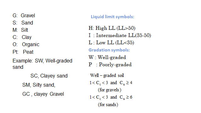
Symbols and other soil properties used for soil classification which are beneficial are given below :
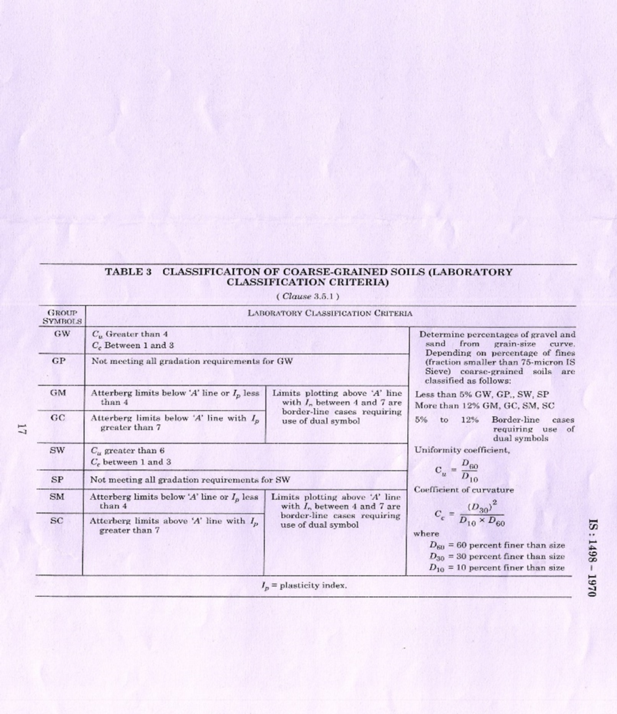
3.Finding Out Cc & Cv
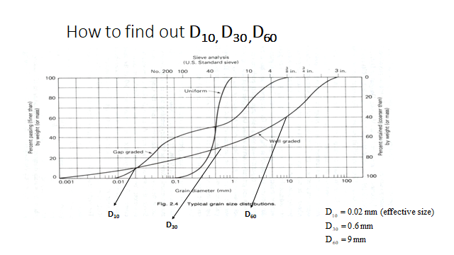
What is D10 , D30 & D60 ?
Practical Definition Of D10: The size of the sieve from which 10 % material are passing. (10% finer than size size)
Practical Definition Of D30: The size of the sieve from which 30 % material are passing. (30% finer than size) •
Practical Definition Of D60: The size of the sieve from which 60 % material are passing. (60% finer than size)
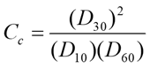
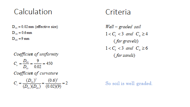
Coefficient Of Curvature
Coefficient Of Uniformity
Both Cuand Cc will be 1 for a single-sized soil.
If Cu> 5 means a well-graded soil means a soil which having particles over a wide size range.
If Ccbetween 1 and 3 it indicates a well-graded soil.
If Cu< 3 it indicates a uniform soil
3.1.Border line (Dual Symbol)
For the below given conditions, a dual symbol will be used.
1.For Coarse-grained soils with PI between 5% – 12% and LL between about 10 and 30). –For Sand it is denoted as SW-SM and for gravel it is denoted as GW-GM.
2.For Fine-grained soils with limits within the shaded zone. (PI between 4 and 7 and LL between 10 and 30 and more clay type materials. CL-ML means Silty clay
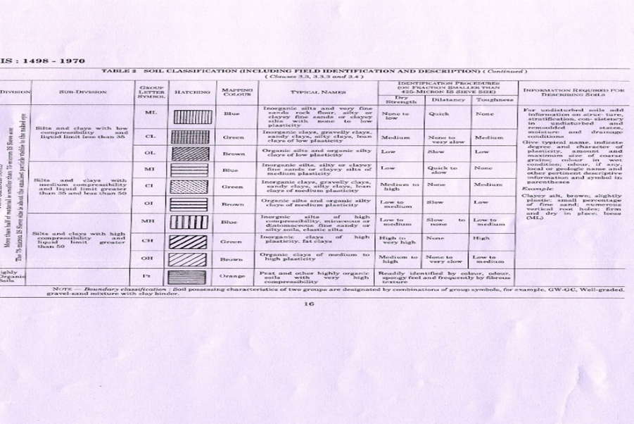
3.2 Organic soil
Organic soils -A sample having decay vegetable tissue in various stages of decomposition and looks like a dark-brown to black color, and smells like organic odor will be designated as organic soil and will be classified as peat, PT.
Organic clay or silt: -“If soil’s liquid limit (LL) after oven drying is less than 75 % of its liquid limit before drying.” it will be organic soil & the first symbol shall be O. -The second symbol can be obtained by locating the values of PI and LL (as usual not oven dried) in the plasticity chart
4.Finding Out Clay(C), Silt( M) & Organic Soil(O) From A Line
We need grain analysis table & 3 sieves are very important i.e 4.75 mm,75 micron and 425 micron(for LL & PL).
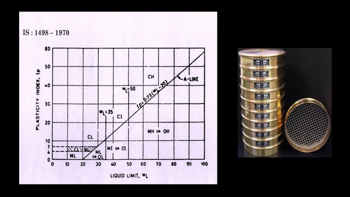
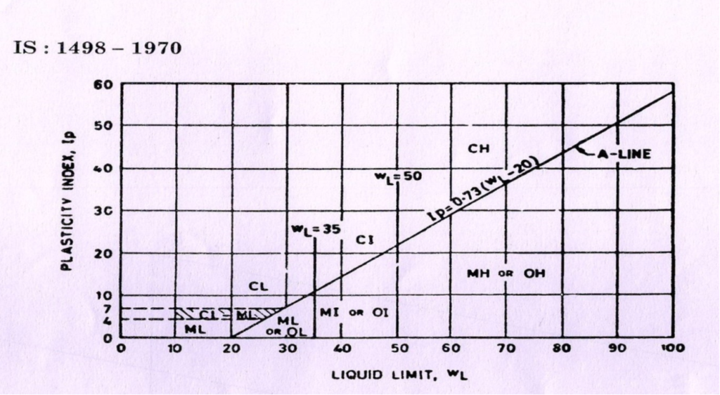
For determining A Line formula A line IP =.73(WL-20) ,The IP obtain from this will be compare from original IP.
Suppose Original IP given is 9.03% and WL is 25.86%.
Find out the A line , A line=.73(WL-20)=.73*5.86=4.28.
Compare it with original IP which is 9.03% which is greater than 4.28% So Sample comes above A line. Above A line will be denoted by C and below A line will be denoted by M or O.
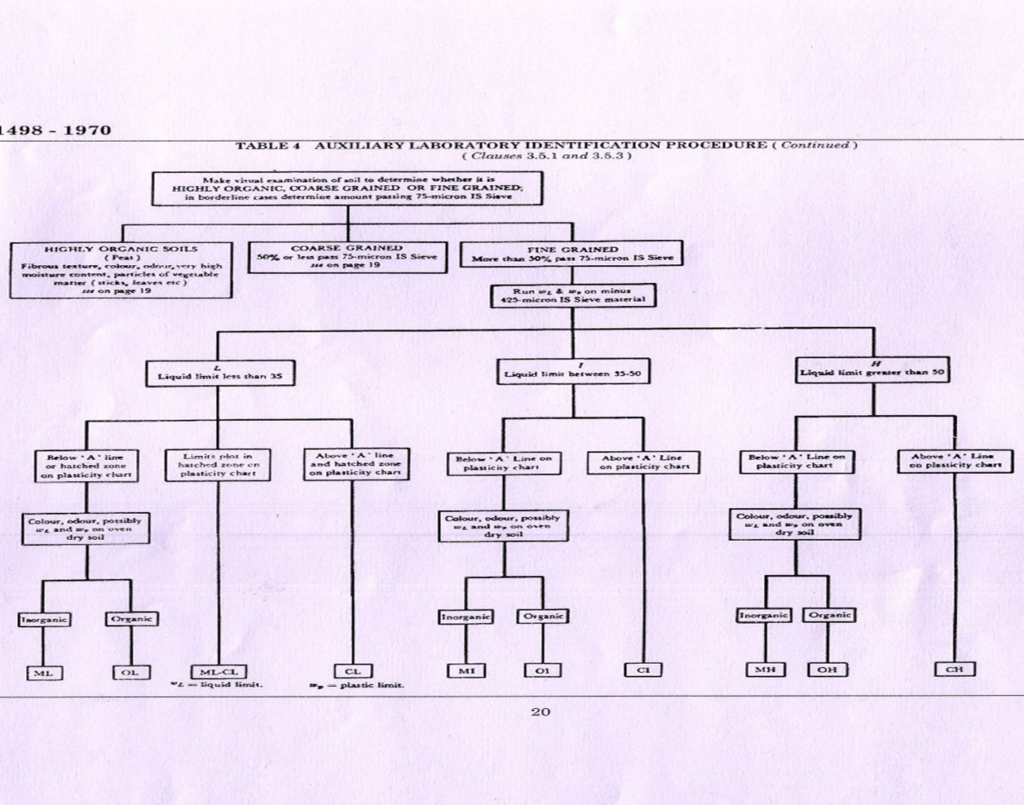
5. Coarse Soil Identification
If 50 % 0r less material is passing from 0.075 mm soil it will be treated as coarse soil & they can be further divided into either gravels (G) or sands (S).According to gradation, they are further symbolized as well-graded (W) or poorly graded (P). If fine soils are present, they can be grouped as silt fines (M) or clay fines (C).
6. Fine Grain Soil Classification
Fine-grained soils are those which passes more than 50% of the material from IS sieve 0.075 mm. A plasticity chart , based on the values of liquid limit (WL) and plasticity index (IP), is provided in IS 1498 to aid classification. The ‘A’ line in this chart has been given by as IP = 0.73 (WL – 20).Any soil which is above A line ; will always be denoted as Clay(C). In the same manner , if soil is below A line ; will be denoted as Silt(M) as discussed earlier in para 4.
Now depending on the point in the chart, fine soils are divided into clays (C), silts (M), or organic soils (O).Three divisions of plasticity are also defined as follows.
If Liquid Limit of the soil is less than 35% ; soil will be classified as CL/ML/OL.If Liquid Limit of the soil is in between 35% & 50% soil will be classified as CI/MI/OI.In the same manner if Liquid Limit of the soil is more than 50% soil will be classified as CH/MH/OH.
Low plasticity means liquid Limit is less than 35
WL< 35%
Intermediate plasticity means liquid Limit is between 35 % & 50 %
35% < WL< 50%
High plasticity means liquid Limit is more than 50%
WL> 50%
Example 1
1.Percentage passing from sieve 4.75mm=38.66%
2.Percentage passing from sieve 0.425mm=37.47%
3 .Percentage passing from sieve 0.075mm=33.47%
4.Liquid Limit =16.80%
5.Plastic Index =.16%
Classify the soil
ANSWER: Less % passing from .075mm sieve so it is coarse grain soil. Less % passing from 4.75mm sieve, hence it is GRAVEL. Its A line=.73*-3.2=-2.336 Sample comes above A line and at .075mm sieve passing more than 12%; so it is classified as GC
Example 2
1.Percentage passing from sieve 4.75mm=68.12%
2.Percentage passing from sieve 0.425mm=56.23%
3 .Percentage passing from sieve 0.075mm=34.62%
4.Liquid Limit =24.5%
5.Plastic Index =N.P Classify the soil
ANSWER:Less % passing from .075mm sieve so it is coarse grain soil. higher % passing from 4.75mm sieve, hence it is SAND. Its A line=.73*4.5=3.285 Sample comes below A line and at .075mm sieve passing more than 12%; so it is classified as SM
Example 3
1.Percentage passing from sieve 4.75mm=99.96%
2.Percentage passing from sieve 0.425mm=97%
3 .Percentage passing from sieve 0.075mm=74.91%
4.Liquid Limit =25.86%
5.Plastic Index =9.03%
Classify the soil
ANSWER:
More % passing from .075mm sieve so it is fine grain soil. Liquid Limit is less than 35% so it is low plastic. Its A line=.73(WL-20)=.73*5.86=4.28.Sample comes above A line so it is classified as CL
Example 4
1.Percentage passing from sieve 4.75mm=99.80%
2.Percentage passing from sieve 0.425mm=99.55%
3 .Percentage passing from sieve 0.075mm=36.10%
4.Liquid Limit =17.54%
5.Plastic Index =N.P
Classify the soil ?
ANSWER:
Less % passing from .075mm sieve so it is coarse grain soil.its % passing from .075mm sieve is more than 12% .Its A line=.73(WL-220)=.73*-2.46= -1.80 Sample comes above A line so it is classified as SC. •
Example 5
1.Percentage passing from sieve 4.75mm=99.96%
2.Percentage passing from sieve 0.425mm=93.87%
3 .Percentage passing from sieve 0.075mm=58.99%
4.Liquid Limit =22%
5.Plastic Index =3.7%
Classify the soil
ANSWER:
More % passing from .075mm sieve so it is fine grain soil. Liquid Limit is less than 35% so it is low plastic.Its A line=.73(WL-20)=.73*2=1.46 Sample comes above A line so it is classified as CL
Example 6
1.Percentage passing from sieve 4.75mm=100%
2.Percentage passing from sieve 0.425mm=94.30%
3 .Percentage passing from sieve 0.075mm=51.54%
4.Liquid Limit =23.0%
5.Plastic Index =4.54%
Classify the soil
ANSWER:
More % passing from .075mm sieve so it is fine grain soil. Liquid Limit is
less than 35% but PI is 4.54 and it comes on hatched line so it is classified ML-CL
Example 7
1.Percentage passing from sieve 4.75mm=82.3%
2.Percentage passing from sieve 0.425mm=73.11%
3 .Percentage passing from sieve 0.075mm=4.82%
4.Liquid Limit =25.42%
5.Plastic Index =8.64%
6.Coefficient of Uniformity =6.66
7.Coefficient of curvature =1.35
Classify the soil
ANSWER: Less % passing from .075mm sieve so it is course grain soil. Greater% passing from 4.75 so it is SAND. Less than 5% passing from .075mm sieve and well graded so it is classified as SW
Example 8
1.Percentage passing from sieve 4.75mm=99.31%
2.Percentage passing from sieve 0.425mm=88.57%
3 .Percentage passing from sieve 0.075mm=50.38
4.Liquid Limit =21.50%
5.Plastic Index =4.84%
Classify the soil
ANSWER:
More % passing from .075mm sieve so it is fine grain soil. Liquid Limit is less than 35% but PI is 4.54 and it comes on hatched line so it is classified ML-CL
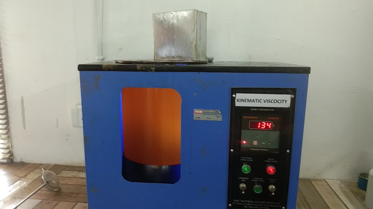
The kinematic viscosity of a liquid is the absolute or dynamic viscosity (poise 60 ° C ) divided by the density of the liquid at the temperature of measurement. The 135° C (275° F) measurement temperature was chosen to simulate the mixing and lay down temperatures typically encountered in HMA pavement construction.The SI unit of kinematic viscosity is m2/s. The CGS unit of kinematic viscosity is the stokes (St).
SCOPE . IS 1206 (part III) covers the method for the determination of kinematic viscosity of paving grade and cut-back It is applicable to the materials having a viscosity range of 30-100000 cSt. Kinematic Viscosity of a Newtonian Liquid. It may be defined as the quotient of the absolute or dynamic viscosity divided by the density of the liquid under test; both at the same temperature. The cgs unit of kinematic viscosity is the stoke which has the dimensions square centimetre per second. For petroleum products the kinematic viscosity is generally expressed in centistokes (cSt) which is 1/100 th of a stoke.
APPARATUS:
Bath :Suitable bath for immersion of the viscometer so that the liquid reservoir or top of the capillary whichever is uppermost is at least 20 mm below the upper hath level.
Timing Device – Any timing device such as stop-watch or stop clock capable of being read up to 0.5 s.
Procedure For Making Bitumen Sample –
Heat the sample to a temperature not more than 90% for bitumen until it attains totally pouring consistency & stir it and transfer approximately 20 ml into a container. Precaution should be taken to avoid over-heating and having any entrapped air .
1.Mount the BS U-tube viscometer in the constant temperature bath keeping tube L vertical.
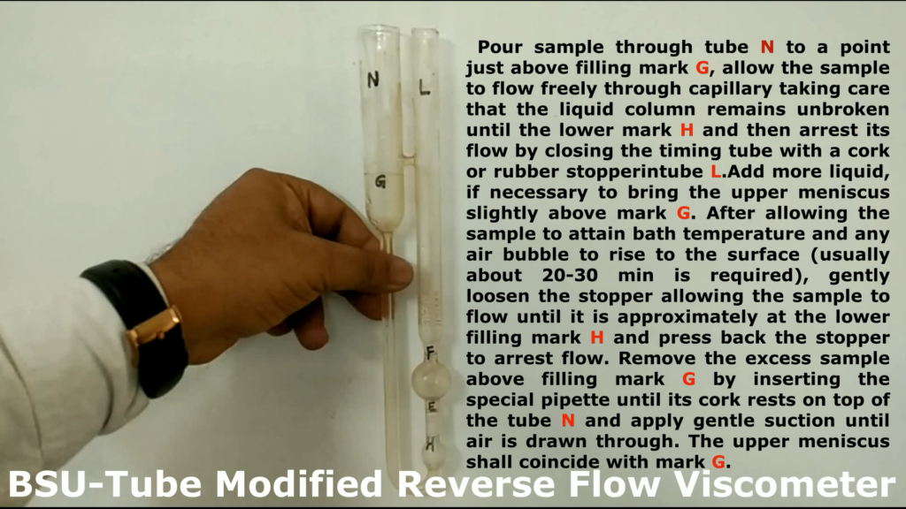
2.Pour sample through tube N to a point just above filling mark G, allow the sample to flow freely through capillary R, taking care that the liquid column remains unbroken until the lower mark H and then arrest its flow by closing the timing tube with a cork or rubber stoppering tube L
3. Add more liquid, if necessary to bring the upper meniscus slightly above mark G. and after allowing the sample to attain bath temperature and any air bubble to rise to the surface .
4.Gently loosen the stopper allowing the sample to flow until it is approximately at the lower filling mark H and press back the stopper to arrest flow.
5.Remove the excess sample above filling mark G by inserting the special pipette until its cork rests on top of the tube N and apply gentle suction until air is drawn through the upper meniscus shall coincide with mark G.
6.Allow the viscometer to remain in the constant temperature bath for a sufficient time to ensure that the sample reaches temperature equilibrium. It takes about 30 min at 135°C.
7.After completion of 30 minutes ,remove the stopper in the tube N and L respectively and allow the sample to flow by gravity.
8.Measure to the nearest 0.1 s the time required for the leading edge of the meniscus to pass from timing mark E to timing mark F.
9. Note down the time .
CALCULATION Calculate the kinematic viscosity up to three significant figures With the help of following equation: Kinematic viscosity cSt=Ct Where C = calibration constant of the viscometer in centistokes per second, and t = efflux time in seconds
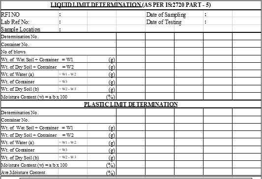
The moisture content at which the cohesive soil passes from a liquid state into a plastic state is called the liquid limit of the soil. Similarly, the moisture contents at which the soil changes its behavior from a plastic to a semisolid state is called as the plastic limit of soil.
Objective
This test is done to find out the liquid limit of soil as per IS: 2720 (Part 5) – 1985. The liquid limit of fine-grained soil is the water content at which soil behaves practically just like a liquid, but have small shear strength. It’s flow closes the groove of 12.7 mm in just 25 blows in Casagrande’s liquid limit device.
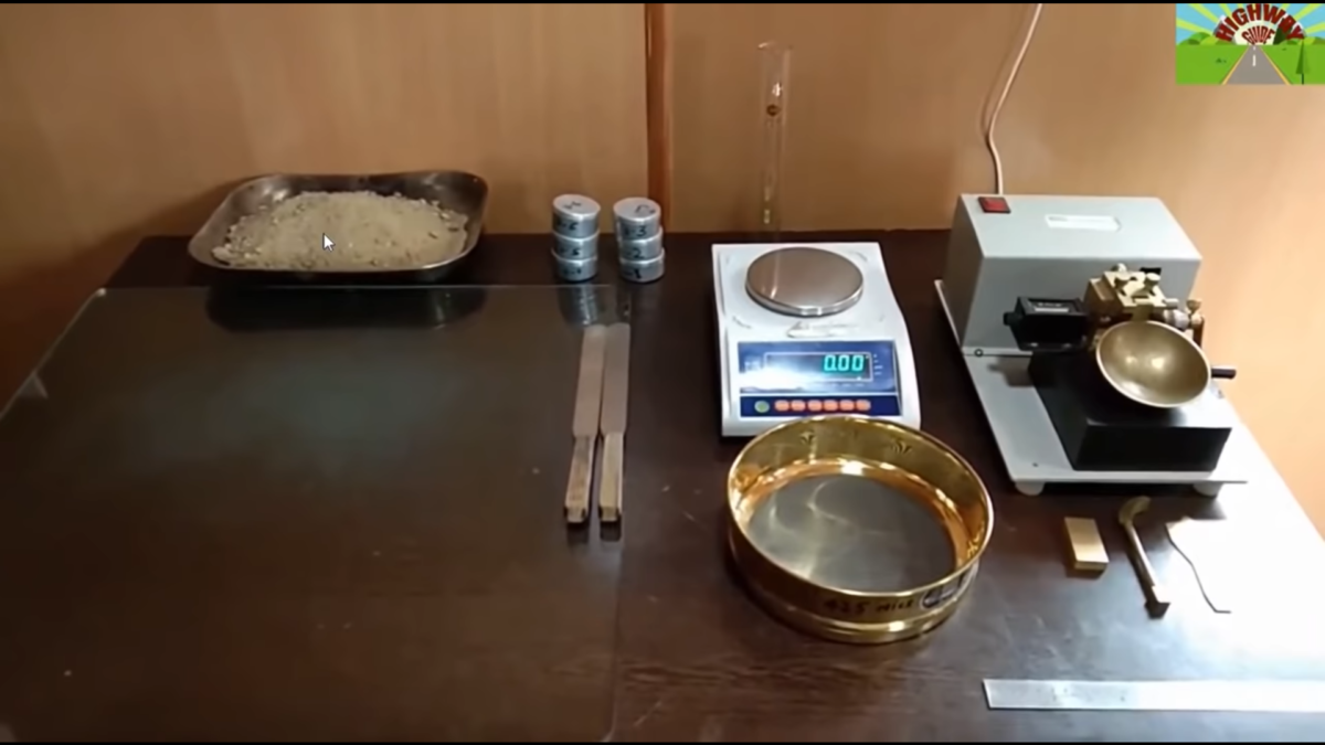
Apparatus
The apparatus used :- i) Casagrande’s liquid limit device ii) Grooving tools both standard and ASTM types iii) Oven iv) Evaporating dish v) Spatula vi) IS Sieve of size 425µm vii) Weighing balance, with 0.01 /1 gm accuracy viii) Wash bottle ix) Air-tight container for determination of moisture content
Preparation Of Sample
i) Dry the soil sample in and break the clods with wooden hammer. Remove any organic matter like tree roots& pieces of bark, etc. ii) Take about 120 g of the specimen passing through 425µm IS Sieve and mixed thoroughly it with distilled water in the evaporating dish and left it for 24 hrs. for soaking.
Procedure
i) Place a portion of the paste into the cup of the liquid limit device.
ii) Level the mix from top so as to have a maximum depth of 1 cm.
iii) Draw the groove from special design tool through the sample along the symmetrical axis of the cup & holding the tool perpendicular to the cup.
iv) For the normal fine grained soil: The Casagrande’s tool is used to cut a groove of 2 mm wide at the bottom, 11 mm wide at the top and 8 mm deep.
v) For sandy soil: The ASTM tool is used to cut a groove of 2 mm wide at the bottom, 13.6 mm wide at the top and 10 mm deep.
vi) After the soil paste has been cut by a suitable grooving tool, the handle of the device is rotated at the rate of about 2 revolutions per second and the no. of blows counted, till the two parts of the sample come into contact for about 10 mm length.
vii) Take about 10 g of soil near the closed groove as a sample for determing its water content.
viii) The soil of the cup is transferred into the dish containing the soil paste and mixed thoroughly after adding some water. Repeat the test as earlier.
ix) By changing the water content of the soil and repeating the foregoing operations & obtain at least 5 readings in the range of between 15 to 35 blows. Keep in mind don’t mix dry soil to change its consistency.
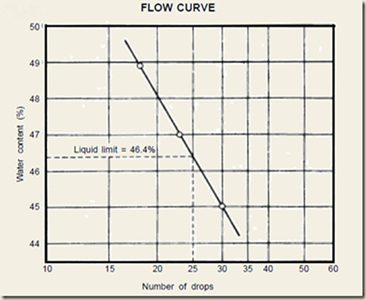
x) Now Liquid limit is determined by plotting a ‘flow curve’ on a semi-log graph, with no. of blows as abscissa X -axis (log scale) and the water content as ordinate on Y axis and drawing the best possible straight line through the plotted points.
Reporting Of Results
Report the water content corresponding to 25 number blows by reading from the flow Curve as the Liquid Limit. A sample of Flow curve is given below for your reference.
Safety: .1 Use hand gloves while opening the door of oven
DETERMINATION OF PLASTIC LIMIT
Objective
For
determination of the plastic limit of soil.
Reference Standard
IS : 2720(Part 5)-1985 Determination of Plastic limit.
Equipment & Apparatus
Oven
Balance with 0.01 g accuracy
IS Sieve of 425 micron
Flat surface glass for rolling
Preparation Of Sample
After receiving the soil sample from the site it is dried in air or in oven ( by maintaining a temperature of 600C). If clods are there in the soil sample it is broken with the help of wooden mallet. The soil passing through 425 micron sieve is used for this test.
Procedure
Take 20 gm soil sample passing from 425 micron IS sieve .
It is then mixed with distilled water thoroughly in the evaporating dish till the soil mass becomes plastic enough to be easily molded with the fingers itself.
Soil should be allowed to season for sufficient time for allowing water to permeate throughout the soil mass.
The 10 gms. of the sample is taken and rolled between fingers and glass plate with just sufficient pressure to roll the mass into a thread of uniform diameter throughout its length. The rate of rolling shall be kept between 60 and 90 stokes per minute.
Continued the rolling till the thread becomes 3 mm. in diameter and see the crumbling.
If not soil is then kneaded together to a uniform mass and rolled again.
The process is to be continued until the thread crumbled and offering shear when rolled into 3 mm diameter.
The pieces of the crumbled thread are collected in a air tight container for determination of moisture content .For more practical see the video given below:
SCOPE : The aggregate impact value provides the property of a relative resistance of the aggregate to sudden shock or impact.
The particular purpose which an aggregate is meant to serve requires the aggregate to have a particular strength which is usually stated in the specification.
APPARATUS : As per IS: 2386 (Part IV) – 1963 apparatus consists of:
i) A aggregate testing machine weighing approximately 45 to 60 kg weight and with a metal base with a lower surface of not less than 30 cm in diameter. It is installed on level plane concrete floor of minimum 45 cm thickness from bottom of the floor.
(ii) A cylindrical steel cup having internal dia 102 mm, depth 50 mm and minimum thickness 6.3 mm.
(iii) A metal hammer having weight between 13.5 to 14.0 kg and its the lower end being cylindrical in shape with 50 mm long, 100.0 mm in diameter, with a 2 mm chamfered at the lower edge and case hardened. The hammer should slide freely between vertical guides and concentric with the cup. Free fall of hammer should be within range of 380±5 mm.
(iv) A cylindrical metal having internal diameter 75 mm and depth 50 mm for measuring aggregates.
(v) A Tamping rod 10 mm diameter and 230 mm long, rounded at one end.
(vi) A balance of capacity not less than 500 gram, with accuracy upto 0.1 g.
PROCEDURE:
1.The test sample should have aggregates sized 10.0 mm & 12.5 mm. Aggregates may be dried at 100-110° C temperature for a period of 4 hours and then cooled at room temperature.
2.Bring the impact testing machine to rest without wedging or packing up on the level plate, block or floor, so that it is rigid and the hammer guide columns are vertical.
3. Fix the cup firmly into position on the base of the machine and transfer whole of the test sample into it and compact it by giving 25 gentle strokes with the tamping rod.
4.Raise the hammer of the machine until its lower face is 380 mm above the surface of aggregate sample in the cup and allow it to fall freely on the aggregate sample and then give 15 such blows at an interval of not less than one second between successive falls.
5.Remove the crushed aggregate from the cup and sieve it through the 2.36 mm IS sieves until no further significant amount aggregate passes in one minute. Weigh the fraction passing the sieve to the accuracy of 1 gm. also, weigh the fraction retained in the 2.36 mm sieve.
6.Calculate the aggregate impact value. The mean of two observations, rounded to nearest whole number is reported as the Aggregate Impact Value of concerned sample.For detailed practical explanation please see the below video.
OBSERVATIONS:
Particular
Sample 1
Sample 2
Total weight of the dry sample ( W1) in gm
Weight of portion passing 2.36 mm IS sieve( W2) in gm