SOUNDNESS TEST OF CEMENT BY LE – CHATELIER METHOD

A cement is said to be unsound if the hydration of a hardened paste of it is eventually accompanied by excessive expansion, causing cracking and reduction in strength.
Accelerated hydration procedures are used routinely in cement production to check that it does not possess this property. The simple apparatus devised by Le Chatelier  is used to indicate the expansion of a paste.Here we will discuss about the practical of soundness test of cement

Standard Used

IS 4031 PART 3

Objective

  • To determine the soundness of cement.

Equipment

  • The apparatus for conducting Le-Chatter test shall conform to IS: 5514 – 1969.
  • Balance of capacity 500 grams and sensitivity 0.01gms.
  • Water bath capable of raising the temperature from 27+ 20C to boiling point in 27 + 3 minutes.

Procedure

  • Take representative sample of cement and mix with 0.78 times the water required to give a paste of standard consistency as per IS: 4031 (Part 4) 1988.
  • Place a lightly oiled mould on a lightly oiled glass and fill it with this cement paste.
  • Prepare the paste in a manner and under the conditions all as per IS: 4031 (Part 4) 1988.
  • Keep the edges of the mould gently together during this operation.
  • Cover the mould with another piece of lightly oiled glass sheet and place a small weight.
  • Immediately submerge the whole assembly in water bath maintained at a temperature of27 + 20C and keep there for 24 hours.
  • After 24 hours remove the mould from the water bath and measure the distance separating the indicator points (E1).
  • Again submerge the whole assembly in water bath at a temperature of 27 + 20C and bring the water to boiling in 27 + 3 minutes and keep it for 3 hours.
  • Remove the mould from the water bath, allow it to cool and measure the distance between the indicator points (E2).
  • The distance between the two measurements indicates the expansion of the cement.
  • Make at least two determinations for each test.

Calculation

  • Calculate the Soundness of cement from the equation given below

Soundness = E2 – E1

E1= Initial distance between the indicator points.

E2= Final distance between the indicator points.

Report

Report the individual and the mean results to the nearest 0.5mm.

Precaution

  • Take care to maintain the temperature of the moulding room, dry material and water within 27 + 20C and the humidity of the laboratory within 65 + 5%.


Facebooktwitterredditpinterestlinkedinmail

Method Statement for Pipe Culvert

1.0 Purpose
This work shall consist of furnishing and installing reinforced cement concrete pipes, of the type, diameter and length as per design and details and at locations shown on the drawings .

2.0 Scope

The scope of work includes the following
Excavation
Head Wall construction
Bedding for Pipe
Laying of pipes
Jointing
Back Filling

3.0 Equipment

Backhoe loader/excavator
Formwork
Transit Mixer
Vibrator
Batching plant
Dewatering Pump, if required
Dumpers

4.0 Materials
All materials used in the construction of pipe culverts shall conform to the requirements of Section 1000 of MoRTH.
Each consignment of cement concrete pipes shall be inspected, tested before incorporation in the work and should conform to IS 458.

5.0 Responsibility
Section Incharge will be responsible for quality control of the section for the construction of Kerb. Further field engineers, surveyors, supervisors and lab technicians will assist him.

6.0 Procedure

6.1 Excavation
The foundation bed for pipe culverts & Head wall shall be excavated true to the lines and grades shown on the drawings
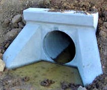
6.2 Head Wall

PCC of specified grade and thickness shall be laid to the specified dimension and level for leveling course below head walls as per approved drawing
The layout of the Head wall shall be made on the PCC as per approved drawing
The formwork shall be fixed to true line, levels, plumb, etc., rigid, adequately braced both horizontally and vertically. Form joints shall be as much as minimized shall be tight and shall not permit any leakage of slurry from concrete.
• Concreting of head wall shall be carried out in two stages according to site conditions.
• first stage shall be done up to bottom of hume pipe.
• second stage concreting shall be carried out. After placing and aligning all the pipes.

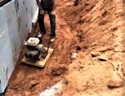
6.3 Bedding for Pipe

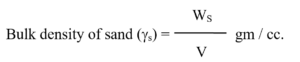
The bedding shall be sand / granular material passing 5.6mm sieve. Specified thickness of granular material bedding shall be provided below the pipes as per the approved drawing. The bed shall be compacted/rammed with adequate water.
In case of high embankments where the height of fill is more than three times the external diameter of the pipe, the embankment should be built first to an elevation above the top of the pipe equal to the external diameter of the pipe, and to width on each side of the pipe not less than five times the diameter of pipe, after then trench for pipe bedding should be excavated.

6.4 Laying of Pipes

• The arrangement for lowering the pipes in the bed shall be done carefully so as not to cause damage or undue strain to the pipes, preferably it shall be done by means of tripod, manual labour or by cranes for loading, unloading & setting the pipes.
• The gap between two rows of pipes shall be at least 450 mm or half the diameter of the pipe, whichever is maximum for new culvert and existing gap shall be maintained for widening of the existing culverts.
• The laying of NP4 pipes shall start from the outlet end & shall be completed at the inlet end to specified lines & grades as specified in the approved drawing.

6.5 Jointing

• The pipes shall be joined by flush joint. The ends of the pipes especially shaped to form self centering joint with a jointing space 13mm wide. The jointing space shall be filled with cement mortar 1:2 sufficiently dry to remain in position. The jointing shall be made with care so that the interior surface is smooth & consistent with the interior surface of the pipe. The joints shall be kept damp for at least four days till the joints are sufficiently hardened.
• The existing head walls shall be dismantled to the required level and dimension as per the approved drawing. New pipe shall be jointed with the existing pipe as shown in the approved drawing.

6.6 Pipe Encasing

Pipe encasing if any, shall be carried out as per the approved drawings .

6.7 Back Filling

Trenches shall be backfilled after the completion of jointing and encasing. The backfill soil shall be free from boulders, large roots, organic soil and any deleterious material and should be approved from the Engineer.Care should be taken while backfilling upto 300 mm above the top of the pipe , the soil should be thoroughly rammed, tamped or vibrated in layers not exceeding 150 mm, special care should be taken while consolidating the materials under the haunches of the pipe. Approved light mechanical means or tamping equipment can be used this purpose.
Filling of the trench should be carried out simultaneously on both sides of the pipe in such a manner that unequal pressures do not occur.
In case of high embankment, after filling the trench upto the top of the pipe , a loose fill of a depth equal to external diameter of the pipe shall be placed over the pipe then after further layers should be added and compacted.

7.0 Quality Control Testing and Acceptance

Quality control tests shall be done as per Sl. No 10 & 14 of Quality Control Tests and Acceptance Criteria .

8.0 Safety & Environment

While working Safety & Environment Procedure shall be followed as per approved EHS Manual.

Facebooktwitterredditpinterestlinkedinmail

Method Statement For Backfilling Behind Abutment & Around Structures.

This Method Statement provides detail of procedure adopted for the construction of backfilling behind structures and abutment.

  • Scope

This work will consist of backfilling behind abutment of bridges and around structures like foundations, underpass, box culvert and other similar structures in accordance with the requirements of these specifications (MoRT&H clause no. 305.4.4) and lines & dimensions shown in the drawing or as indicated by the Engineer.

  • Material

Approved material will be used as a backfill material from approved sources. Fill material shall be free from logs, stumps, roots, rubbish or any other ingredients likely to deteriorate or affect the structure.

  • Responsibility

Section In charge will be responsible for quality control of the section for the backfilling work. He will liaise with Concessionaire Engineer In Charge. Further he will be assisted by field Engineers, Surveyors, Supervisors and lab technicians.

  • Equipment

The following construction machineries will be deployed for backfilling work.

Dumper / trucks

Grader

Small Vibratory Roller

Water tanker

Plate Compactor

  • Procedure
    • Backfilling around structures

Backfilling will be done with approved material after concrete or masonry is fully set and carried out in such a way as not to cause undue thrust on any part of the structure. All spaces between foundation, masonry or concrete and sites of excavation will be backfilled. Fill material will be spread in layers manually or by grader in layers of uniform thickness not exceeding 250mm compacted thickness over the entire width of the structure. Each layer of approved materials will be thoroughly compacted after necessary watering by means of small vibratory rollers/plate compactor or thoroughly rammed in small areas where mechanical means cannot be deployed. Successive layers will not be placed until the layers under construction have been thoroughly compacted to the specified requirement of table 300-2, i: e; 95% and 97% of MDD at OMC for embankment and sub grade respectively.

  • Backfilling Behind abutment and Wing wall

Filling behind abutments and wing walls for all structures without weep-hole, will be done with approved filling material. The fill material will be deposited in loose thickness and compacted after necessary watering up to a thickness of 250mm, until the required compaction of 95% & 97% of MDD at OMC achieved, for embankment & sub grade respectively. Filling will be carried out in equal layers on each side of the structures to avoid displacement and unequal pressure.

Where provision of any filter media is specified behind abutment (where weep-hole exists), filter media as designed will be laid and compacted after necessary watering up to a compacted thickness of 250mm until 95% & 97% of MDD at OMC achieved, for embankment & sub grade respectively. The material used for filter media will conform to the requirement for filter medium spelt out in clause 2504.2 / 309.3.2.

If impracticable to use conventional rollers, the compaction will be carried out by mechanical means like small vibratory roller/plate compactor. Care will be taken to see that, the compaction Equipment does not hit or come too close to any structural member, so as to cause any damage to them or excessive pressure against the structure.

  • Quality Control and Testing

Quality control tests shall be done as per Sl. no. 1 of Quality Control Tests and Acceptance Criteria

  • Safety & Environment

While working Safety & Environment Procedure shall be followed as per approved EHS Manual.

Facebooktwitterredditpinterestlinkedinmail

DETERMINATION OF DRY DENSITY OF SOILS IN PLACE (SAND REPLACEMENT METHOD)

Soil compaction is a artificial method in which expulsion of air from soil is done by mechanical means thereby increasing the density of soil In construction.
It is important to know and control the soil density during compaction process .To determine the proper soil compaction of embankment or subgrade in highway project , several methods were developed.The most prominent method is Sand Replacement method to check the relative density at site.In this article ,we will discuss in detail “how to perform sand replacement test at site”.

STANDARD USED 

IS: 2720 (Part 28) 1974.

OBJECTIVE

To determine the in place dry density of natural or compacted fine and medium grained soils by sand replacement method.

APPARATUS

  1. Small sand pouring cylinder for depth up to 150 mm.
  2. Large sand pouring cylinder for depth more than 150 mm and not exceeding 250 mm.
  3. Tools for excavating holes such as a scraper tool for leveling the surface, bent spoon or dibber for digging holes.
  4. Cylindrical calibrating container with material diameter of 100 mm and an internal depth of 150 mm.
  5. Balance of capacity 15 kg and sensitivity 1 gram.
  6. A glass plate o about 600 mm square area and atleast 10 mm or more thicker.
  7. Metal containers.
  8. Metal tray  having area 300 mm square , 40 mm deep with a 100 mm hole in the center of the tray.
  9. 1 mm and 600 microns IS sieves..
  10. Clean, uniformly graded natural sand passing 1 mm sieve and retained on 600 microns sieve.

PROCEDURE

Calibration of Sand Pouring Cylinder

  1. Clean and dry, sand passing 1 mm sieve and retained on 600 microns sieve approximately 5 to 6 kg for small pouring cylinder and 23 to 24 kg of sand for large pouring cylinder.
  2. Remove the cap of the pouring cylinder.
  3. Weigh the empty pouring cylinder (W).
  4. Close the shutter of the cone.
  5. Fill the sand in to the pouring cylinder about 10 mm below from the top.
  6. Determine the net weight of sand in the cylinder (W1).
  7. Now place the pouring cylinder on a clean plane surface, open the shutter and allow the sand to flow in to the cone.
  8. Close the shutter when the flow stops.
  9. Carefully collect and weigh (W2) the sand discharged from the pouring cylinder.
  10. Refill the pouring cylinder with sand such that the initial weight is W1.
  11. Place the pouring cylinder on the top of the calibration cylinder concentrically.
  12. Open the shutter and allow the sand to flow in to the calibrating cylinder.
  13. Close the shutter when the flow stops or no further movement of sand takes place in the cylinder.
  14. Determine the weight (W3) of the pouring cylinder.
  15. Repeat the above procedure for at least three times and determine the mean values of W2 and W3.
  16. Determine the volume (V) of the calibrating cylinder either by measuring the dimensions
  17. (Diameter and height) or by filling with water until the brim.

CALCULATIONS

Weight of sand (WS) in the calibration container up to level top

WS = W1 – W3 – W2 grams

Volume of calibrating container = V cc

DETERMINATION OF SOIL DENSITY

  1. Prepare a flat approximately 450 mm square area with the aid of a scraper tool.
  2. Place the metal tray just above the central hole on the prepared surface of the soil to be tested.
  3. Excavate the hole in the soil with a chisel & hammer using the hole in the tray as a pattern to the depth of the layer to be tested.
  4. Carefully collect the excavated soil from the hole and weigh (Ww).
  5. Determine the water content (W) of the excavated soil as per IS: 2720 (Part 2) 1973.
  6. Fill the pouring cylinder to the constant weight (W1) i.e. weight equal to the initial weight during calibration.
  7. Remove the metal tray before the pouring cylinder is placed in position over the excavated hole.
  8. Place the cylinder such that the base of the cylinder covers the hole concentrically.
  9. Open the shutter and allow the sand to run out in to the hole.
  10. Close the shutter of the pouring cylinder when no further movement of sand takes place in the cylinder.
  11. Remove the cylinder and determine the net weight of sand (W4).

CALCULATIONS

REPORT

  • Report the bulk density and dry density of soil to the nearest second decimal.

PRECAUTIONS

  1. Care shall be taken to see that the test sand used is clean, dry and uniformly graded.
  2. Care shall be taken in excavating the hole to see that the hole is not enlarged  against the side of the hole, as this will result in lower densities.
  3. Care shall be taken to see that the same initial weight of sand is taken during calibration and during density measurement in the field.


Facebooktwitterredditpinterestlinkedinmail