HOW TO CONVERT 1:2:4 FROM VOLUME TO WEIGHT

A frequent question arriving in my email mailbox is “HOW TO CONVERT 1:2:4 FROM VOLUME TO WEIGHT ?” Most commonly, people are trying to find out how to convert from volume to weight  so in this article I am giving detail procedure for to convert from weight to volume.

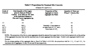
For clarification I am taking table 9 from IS 456-2000

HOW TO CALCULATE

Calculation of materials required for 1 m³

Density of Cement = 1440 kg/cum

Volume of 01 bag (50 kg) of cement = 50 /1440 = 0.035 cubic meter (cum)

We know the ratio 1:2:4

Volume of Sand required would be = 0.035*2 = 0.07 cubic meter (cum)

Volume of Aggregate required would be = 0.035*4 = 0.14 cubic meter (cum)

Next step , you have to convert the volume and check for the feasibility from IS 456-2000  provision means water cement ratio maximum 32/50 =0.64 and all ingredient(coarse aggregate fine aggregate should not be more than 330 kg.

CONVERT VOLUME TO WEIGHT

For converting volume to weight you need dry loose bulk density , which can be determine by density box. Here we are assuming For sand 1450 kg/m³ and for aggregate take 1550 kg/m³.

Quantity of sand will be 0.07 x 1450 = 101.50 kg

And quantity of aggregate 0.14 x 1550 =217.0 kg

Cement =50 kg

And take W/C ratio 0.60 Water 0.60 X 50 = 30.0 kg but specified water is 32 kg hence O.K.

Specified All in aggregate should not be more than 330 kg(318.0 kg), hence O.K

So, One bag of cement (50 Kgs) has to be mixed with 101.50 kgs of Sand, 217.0 Kgs of aggregate and 30 kgs of water to produce M15 grade concrete.

MATERIAL REQUIRED FOR I M³

From the above calculation, we have already got the weights of individual ingredients in concrete . So, the weight of concrete produced with1 Bag of cement (50 Kgs)

=50 kg + 101.5 kg + 217 kg + 30.0 kg = 398.5 kg say 400 kg

Considering concrete density = 2400 kg/cum,

One bag of cement and other ingredients can produce = 400/2400

= 0.1667 m³ of concrete (1:2:4)

01 bag cement yield = 0.166 cum concrete with a proportion of 1:2:4

01 cum of concrete will require Cement required = 1/0.166 = 6.02 Bags Say 6 bags

Sand required = 101.5/0.166 = 611.44 Kg or 611 kg

Aggregate required = 217/0.166 = 1307.28 kg or 1307 kg

Water =30.0/0.166= 180.72 say 181 kg

INGREDIENT REQUIRED FOR 1:2:4 IN 1 M³ IN Kg

  • Cement 300.0 kg
  • Sand 611.0 Kg
  • Aggregate 1307.0 Kg
  • Water 181.0 kg
  • If ratio of 20 mm & 10 mm is 60% and 40%
  • Then 20 mm 1307 x 60%= 784 kg
  • 10 mm 1307 x 40%=523 kg
  • In the same manner you can calculate for M20
Facebooktwitterredditpinterestlinkedinmail

DOCUMENT CONTROLLING PROCEDURE

Documentation relating to all project activity is prepared and maintained by
each organizational element. Such documentation will provide accurate and
current information on all project activities and for all information which contributes to the understanding of the project. Records are reviewed by appropriate personnel and provided to all concerned organizational elements. Procedure for documentation and record maintenance and retention are given as below:

1. SUMMARY
1.1. This procedure defines the requirements for the creation, review, approval, distribution, use and revision of quality management system documents.
1.2. This procedure applies only to documents which instruct office/site staff on how to carry out activities and tasks; this includes manuals, procedures, forms and instructional sheets or posters.
2. PROCEDURE
2.1. Creation of Documents
2.1.1. Documents are created by an appropriate subject matter expert.
2.1.2. All internal documents are created as soft files (MS Word®, etc.); it is recommended that files of a similar type follow the format of other documents in that type.
2.1.3. Draft versions must then be sent to the appropriate approver(s) for review and approval.
2.1.4. Original releases of documents are given a revision indicator of “0”.
2.2. Review and Approval
2.2.1. The Quality Manual may only be approved by the senior Management. Other documents are to be approved by the original author, or a company executive.
2.2.2. Draft files may be sent to the approver(s) via hard copy or e-mail.
2.2.3. The reviewer will resolve any issues with the original author to achieve a satisfactory document.
2.2.4. The reviewer will indicate approval of the document by e-mail.
2.2.5. The approved document shall then be forwarded to the Document Controller .
2.2.6. If hard copy binder will be used , document Controller , will maintain a binder of most current hard copy versions of documents.
2.2.7. The Document Controller will maintain a computer folder, on the company server, for the latest soft copy versions of document with backup facility. The Document Controller Title will place new or revised documents into that folder, Any previous soft versions are then moved to a separate folder identified for obsolete documents which are kept for historical purposes.
2.2.8. The directory of official released documents shall act as a “master list” of documents, indicating the setting each file’s permission to READ ONLY, or converting the released versions to a non-editable file format.
2.2.9. current versions of all documents. No other master list is required.
2.3. Distribution of Documents
2.3.1. If intranet is used, Controlled documents will be available via the intranet for all employees.
2.3.2. If hardcopy document distribution is used, the Document Controller will maintain a list of where controlled hardcopy documents are to be distributed. The Document Controller will be responsible for distributing updated copies of such controlled hardcopies to proper locations. Controlled hardcopies shall be marked with stamp in color ink on the first page as CONTROLLED, to distinguish them from uncontrolled documents or photocopies.
2.3.3. Controlled hardcopies may not be altered or modified by users, and must remain legible and readily identifiable. This includes hand mark-ups by unauthorized personnel. Controlled hardcopies may not be photocopied, unless for the purposes of sending to a recipient who is authorized to receive uncontrolled versions of Project documents (i.e., a vendor or customer).
2.4. Re-Evaluation
2.4.1. Documents must be reviewed by the original author or another subject matter expert or top manager as required.
2.4.2. The Document Controller will ensure re-evaluation is conducted and that documents are updated if required. The Document Controller will maintain a record of document re-evaluations of any process, to identify when documents are due for re-evaluation.
2.4.3. If a document is determined to require updating, the changes shall be made and a new version issued per the rules below.
2.4.4. If a document is determined not to require updating, no action on the document is necessary.
2.5. Revising Documents
2.5.1. Changes to documents go through the same steps as original issue, except that their revision level is advanced upon approval.
2.5.2. Only authorized personnel may change documents, although any employee can request a change to their Manager, or other document change request form. All the revised document shall include a change history table within its text.
2.5.3. Any changes to documents require authority review and approval shall be submitted accordingly, and not implemented until such approval is obtained.
2.5.4. If document changes require regulatory approval prior to implementation, this will be obtained in writing & reflect the reason for the change.
2.5.5. Re-evaluation, inspection (where applicable) and internal auditing will confirm the effectiveness of changes.
2.6. Controlling Documents of External Origin
2.6.1. For external documents such as standards or third party specifications which are referenced in a customer purchase order or contract, these documents may be maintained without control.
2.6.2. For external documents such as standards or third party specifications which are not referenced in a customer purchase order or contract, these must be controlled. Such control requires that the Document Controller or responsible manager obtain the latest version of the document, and maintain it on the company server (for electronic versions) or in a binder of controlled external documents (for hardcopies). Like other controlled documents, these may not be edited or copied.
2.6.3. Third party specifications and prints, including those of the customer, are controlled per the configuration management requirements set forth in the Quality Manual .
2.6.4. External documents for non-critical use, such as user manuals, reference books, marketing materials, and supplier directories are not controlled.
2.7. Forms
2.7.1. Forms are a special kind of document that may be photocopied as needed. A softcopy of each approved form should be sent to document controller for his record for inclusion in the Document Master List .

Facebooktwitterredditpinterestlinkedinmail

HOW TO CURE CONCRETE CUBE

As all over the world concrete is accessed by its compressive strength so curing of concrete cube in a proper manner having great importance .Concrete cube can be cured in a following manner:

  1. Leave the test specimens in the mould for at least 16 h, but not longer than three days, from the time of addition of water to the dry ingredients. Protect the specimens from shock, vibration and water evaporation. Store the specimens at a temperature of 27 ± 3 °C.
  2. After removal from the mould, submerge the test specimens in clean, fresh water immediately. Store the test specimens in water at a temperature of 27±2°C and take it out just prior to testing. Alternately, store the test specimens in a chamber at a temperature of 27 ± 2°C and a relative humidity of at least 95 percent until just before testing.
  3. If the test specimens are to be sent to a test laboratory, cover the test specimens with wet cloth or wet sand/ sawdust or other suitable material or seal the test specimens in plastic bags containing water to ensure that the test specimens are delivered to the test laboratory in damp condition not less than 24 h before the time of testing. At the test laboratory, store the test specimens in water at a temperature of 27 ± 2°C until taking it out just prior to testing.
Facebooktwitterredditpinterestlinkedinmail

Calibration Procedure Of Equipment

  1. SUMMARY
    • The aim of this procedure is to define the necessity for calibration or verification of equipment which can be used to determine the acceptability of product.
    • The QA/QC Head will be responsible for implementation and management of this procedure.
  1. PROCEDURE: CALIBRATION
    • Devices subject to calibration shall be calibrated by an approved outside service provider, or by trained employees.
    • Third party calibration laboratories should be accredited to NABL whenever possible, as this provides the best control of calibration activities, and traceability to national standards.
    • When staff perform in-house calibration, this shall be performed in accordance with documented procedures for each & every type of calibration performed.
    • Traceability to the national standards should be maintained for all devices where such traceability is possible .
    • Approved calibration service providers should maintain suitable environmental conditions for calibration such as temperature and relative humidity on any calibration test certificates. For in-house calibration, the QA/QC head will ensure suitable conditions for calibration.
    • The Calibration log will be maintained by the QA/QC Engineer. This document will contain the list & make of all devices with serial number, date of last calibration, and next calibration due date. All calibrated certificates must have the identification of any standards used by the calibration house, and their serial numbers, allowing for traceability to Client/ Independent Engineer.
    • For tools calibrated in-house by EPC contractor staff, the results and standards used shall be recorded on the Calibration Record and shall include any standards and/or procedures uses.
    • Calibrated devices should contain a calibration sticker that includes the current calibration status, calibration due date, and device identification number. Where the device cannot accommodate a calibration sticker due to size or frequency of use, the device shall be numbered and the QC Manager shall keep a log of those devices and their status.
    • QC Manager shall submit expired tools to QC Head for recalibration, and he shall positively recall such expired tools for recalibration.
    • An “amnesty window” of 1 week is allowed beyond the due date marked on the device, to accommodate arrangement of calibration or verification, or for production capacity purposes.
    • Devices in use for noncritical measurements are to be marked REFERENCE ONLY.
    • Any device failing to satisfy calibration standards will immediately be taken out of service. The device may then be sent out for repair. Repaired devices must be calibrated before being returned to service.
    • When a measuring device is found to be out of tolerance, and/or reported on the calibration certificate of having been found as “defective” or “out of tolerance” by the third party provider, QC Manager shall be notified immediately. The QC Head shall oversee a study to find out the impact of the out-of-tolerance device on product shipped.
  2. VERIFICATION
    • Where a device cannot be calibrated against traceable standards, it must be verified against some known-good object or method and proven as acceptable.
    • Known-good objects must be protected so their status is not altered, either by physical damage or deterioration.
    • Known-good methods must be documented in procedures, with a rationale for their acceptability being documented.

Facebooktwitterredditpinterestlinkedinmail

DESIGN CONTROL PROCEDURE

1.SCOPE: This procedure identifies design processes that require process control.

2.SUMMARY: The design control is essentially intended for controlling all activities of design planning, design preparation, verification , review and validation so that the final product meet specified requirements .

3.DIFFERENT STAGES OF DESIGN : Following activities covering the different stages of the project:

  • Traffic Survey
  • Inventory and Condition Survey Of Road , Bridges and Culverts
  • Topographic Survey
  • Axle Load Survey
  • Benkleman Beam Deflection Test , If Required.
  • Soil and Material Investigation.
  • Geo-Technical and Sub Soil Investing.
  • Checking , Approval and Filling of Calculation.
  • Review , Approval , checking & verification of Design Outputs.
  • Control of design changes and validation of design.

4.PROCEDURE :

  1. All the activities of project design has been undertaken by ………authorized consultant.
  2. After going through all the procedure above mentioned, the design consultant will submit the design report to the concessionaire.
  3. Concessionaire shall review the design for the suitability & project specific requirement.
  4. If found suitable, analyse the cost calculation and time frame to complete the project in stipulated time frame.
  5. After approval from the management, concessionaire shall submit the design to independent consultant for the review and necessary suggestion.
  6. After review, concessionaire will see the feasibility, if found suitable implement the same for the project.
  7. During execution ,from time to time, keep an eye over the design for practical feasibility, if not matching with the site condition , go for the revision & repeat the process mentioned above.


Facebooktwitterredditpinterestlinkedinmail

Contract Review Procedure

1. Summary
1.1. This procedure defines the process and methods of reviewing contract , and for verifying the project which meets the requirements.
1.2.The contract department is responsible for implementation and management of review activities.

2. Procedure
2.1.Once the contract has been awarded, the Estimating Department generates a “Contract and Specification Review” form which contain the following:
• The contract
• Specifications
• Specific documents and requirements related to production
• General notes
• Project specific work instructions & Circular
• Requirements from the contract or specification that vary will be highlighted, and copies of that will be distributed to the appropriate processing departments.
• Once the designated departments have reviewed the documents, they will sign in the appropriate space, commenting if desired, and return to the QS department. A completed “Contract and Specification Review” sign-off form will demonstrate a complete review.
2.2. Throughout the project, revisions to contract documents will be reviewed with the original Estimate and the Project Coordinator will ensure compliance with the contract documents. The potential cost and/or schedule impacts to the project will be determined based on any changes.
2.3. These subsequent reviews are documented by memo or other suitable means and are routed with a new generated form to any function that is affected by the change to inform and solicit input. The final result’s filed within the job folder.
2.4. The QS department will attach the completed form to the Estimator’s budget sheet(s) and place them in the job folder. The job folder is then furnished to the Project Coordinator for project assignment.
2.5. The Project Coordinator/Vertical head will assign a Job Number to the project and make four copies of the form and re-distribute to all functions.

Facebooktwitterredditpinterestlinkedinmail

GIRDER LAUNCHING

Transportation, unloading and erection of the precast prestressed concrete girders shall be done under the direction of  experienced  engineer  he should be present for all stages of girder loading, unloading and erection. We have divided all these process into 7 sections

1.OBJECTIVE:

This methodology describes a detailed procedure for the erection of PSC Girders. Minor changes to the methodology would be adopted to suit the site conditions.

2.SCOPE OF WORK:

The scope of this methodology covers Lifting, Transportation and Erection of PSC Girders for all Flyovers & Bridges.

3.RESPONSIBILITY:

The responsibilities of the entire operation shall be assigned to a Senior Officer of the company who shall take care as an In-charge regarding all

4.MANPOWER: 

  1. A) Personnel to be deployed for smooth conducting work
  2. Section In charge-01 No’s
  3. Site Engineer/Site Supervisor-01 No’s
  4. Fore Man-01 No’s
  5. Segment man-02 No’s
  6. Rigman-04 No’s
  7. Kalasi-06 No’s
  8. Crane Operator-2 No’s
  9. Hydra Operator-2 No’s
  10. B) Personnel to be deployed for safety during work 
  1. Officer Safety-01 No’s
  2. Supervisor Safety-01 No’s
  3. Marshal Man -02 No’s

5. MACHINERIES :

  1.  Modular Trailers with capacity of 60 MT (2 Nos.).
  2. Tyre mounted 180 MT crane with Telescopic or Lattice Boom (2 Nos.)
  3. Tyre mounted mobile 80 MT service crane (1 Nos.)
  4. Pilot van (1 No.)

6.0 CONSTRUCTION METHODOLOGY

6.1     PREPARATION OF SITE AT ERECTION POINT:-

Following points to be ensured:-

  1. The site of erection and the approach to be leveled, dressed and rolled (if required) so that the machineries viz; cranes and trailers move and can be placed on s firm ground in correct position.
  2. Overhead obstruction (if any) to be removed.
  3. Adequate Area lighting to be provided for work at night.
  4. Proper and safe access to be arranged for supervisory staff to climb up to the top of Pier Cap to check correct alignment/ level of girder when erected.
  5. All lifting tackles viz; Slings, D- Shackle, U clamp ropes and temporary packing viz. wooden block etc. to be checked regarding the Quality/ Soundness and kept near site.

6.2     LOADING OF GIRDER AT CASTING YARD:-

Following points to be ensured:-

  1. The girders are to be loaded at the casting yard either by the help of Mobile Cranes.
  2. The site where the girders are to be loaded on to the trailer to be dressed leveled and rolled (if required) for smooth and safe movement of trailers and cranes.
  3. After girder is loaded on to the trailers, the same is to be securely tied at two ends (near support) so that the same doesn’t tilt during transportation.
  4. Girders to be loaded for erection are to be identified and checked carefully regarding length etc. so that there is no mistake regarding the sequence to erection.
  5. The engineer shall check the identification mark, length and finishing of girders before loading on to trailers.
  6. Lifting tackles viz; slings etc. to be checked and sleepers/ packing are to be kept in correct position before placing the girders on to the trailer.

6.3     ERECTION OF GIRDER:-

  1. Before starting erection work the positions of trailer and the cranes are to be ascertained carefully to ensure that during lifting, swinging and placing on to the pier cap is done smoothly.
  2. Before lifting the girders, the Radius and Angle of the crane booms to be checked to ascertain safe lifting capacity during erection.
  3. The outriggers of the cranes must have proper supports/ packing so that during lifting, swinging and placing the girder, cranes remain stable.
  4. Once the girder gets lifted from the trailer, it is to be moved out from the erection site so as to provide adequate space during erection.
  5. The girders thus being erected to be placed directly on the Neoprene Bearing (which are to be fixed prior to erection in correct position and level). In-case the girder cannot be placed directly on the bearing the same is to be placed on Pier Cap on wooden sleepers and shifted to correct location by changing the position of the cranes.
  6. Before removing the slings from the erected girders it is important to temporarily support the girders by the help of proper diagonal supports. When the second girder is erected in position immediate arrangement is to be made to tie two girders at the support and at the middle by proper tie member (i.e. Channels, Angles etc.).
  7. The position of the cranes is to be changed for erection at each girder suitably as required.
  8. Once all girders for one carriageway are lifted and placed in positions, cross diaphragm are to be cast so that temporary ties can be removed.

 7.0     SAFETY:

Safety during lifting, loading, transportation and erection is the most important and primary consideration of the entire operation. The following points need to be checked and ensured:-

  1. Capacity of cranes, trailers, lifting devices and packing (wooden blocks) to be ascertained before use.
  2. The approach for the cranes and trailers both at the loading and erection point must be leveled, dressed and rolled to ensure smooth and safe movement.
  3. During transportation/ movement of cranes all care to be taken to ensure smooth traffic flow on the highway.
  4. A Pilot van with flag/ batten light must escort the cranes and trailers during their movement.
  5. Safety officer along with traffic marshals must be available during the entire operation to ensure safety.
  6. All persons engaged must use P.P.Es viz. helmets, belts, gloves, shoes, jackets etc.

Facebooktwitterredditpinterestlinkedinmail

PLASTIC SHRINKAGE CRACK

In simple way ,when fresh concrete has been placed in forms, concrete undergoes a volumetric contraction while it is in plastic state (before the concrete has set). This is known as Plastic Shrinkage,

Plastic Shrinkage are so-called because they form while the concrete is still plastic, ie has not set. Rapid drying of the surface of the plastic concrete causes it to shrink and crack.They rarely occur near the edges of a slab as at those locations the concrete is usually free to move.It can starts after 30 minutes of concrete pouring or during finishing.Plastic shrinkage cracking rarely impairs the strength of a concrete element.  

Main factors affecting plastic SHRINKAGE

  • The main reason behind plastic shrinkage cracking is considered to be rapid and excessive surface water evaporation of the concrete element in the plastic stage (freshly cast concrete) which in turn leads to the so-called plastic or capillary shrinkage1. Water/cement ratio: Low water cement ratio resulting high strength mixes resulting in early plastic shrinkage crack.2. Additives(Effect of superplasticizer on cracking): Higher doses of SP resulting in early crack.  3. Fines Content: More fines is liable to get plastic shrinkage crack.

    4. Depth of the concrete section: Deeper concrete section is less prone to plastic shrinkage cracking

    5. Curing measures- Poor or inadequate curing

    6. Effect of coarse aggregate content on cracking – Reducing the amount of the coarse aggregate in concrete mix leads to more plastic shrinkage and higher cracking risk.

    7. Type of cement – OPC 53 grade cement is very fine grinding and need more water to hydrate & liable to get crack.

    Practice To Minimize The Plastic Shrinkage Crack

  • To minimize the incidence of plastic shrinkage cracking: Dampen the subgrade and formwork , ensuring that any excess water is removed prior to placing concrete.
  • In hot weather, lower the temperature of the fresh concrete by using chilled mixing water  or any suitable method.
  • Do the concrete work , when temperature is below 35˚ C
  • Protect concrete surfaces from drying out by gunny bags or suitable means
  • Commence curing regime promptly after finishing and continue for the specified period.
  • Revibrate the concrete or use towel with pressing into the concrete and make finish before hardening the concrete.          
Facebooktwitterredditpinterestlinkedinmail

DETERMINATION OF QUANTITY OF WATER ADDED , FOR REQUIRED COMPACTION OF SUB GRADE & EMBANKMENT

Example: A soil in the borrow pit is at a dry density of 17 kN/  with a moisture content of 10%. The soil is excavated from this pit and compacted in a embankment to a dry density of 18 kN/  with a moisture content of 15%. Compute the quantity of soil to be excavated from the borrow pit and the amount of water to be added for 100   of compacted soil in the embankment. 

Ans :Volume of compacted soil = 100  m³ & Dry density of compacted soil = 18 kN/m3

Weight of compacted dry soil = 100 × 18 = 1800 kN. This is the weight of dry soil to be excavated  from the borrow pit.

Weight of wet soil to be excavated = 1800 (1 + w) = 1800 (1 + 0.10) = 1980 kN.

 Wet density of soil in the borrow pit = 17 (1 + 0.10) = 18.7 kN/ m³

Volume of wet soil to be excavated = 1980 / 18.7  = 105.9  m³

Moisture present in the wet soil, in the borrow pit for every 100  m³ of compacted soil

 = 1800 × 0.10 = 180 kN

 Moisture present in the compacted soil of 100  m³ = 1800 × 0.15 = 270 kN

 Weight of water to be added for 100  m³ of compacted soil = (270 – 180) kN = 90 kN

= 90/ 9.81   m³  = 9.18 kl

Facebooktwitterredditpinterestlinkedinmail