ABSOLUTE VISCOSITY OF BITUMEN AS PER IS 1206 PART II

Scope

This standard (part II) covers the method for the determination of absolute viscosity of bitumens and cut-backs by vacuum capillary viscometers at any specified temperature. It is applicable to materials having a viscosity range of 42 to 200 000 Poises.

APPARATUS

a.Viscometer Cannon-Manning Vacuums Viscometer

b.Thermometer – The thermometer shall be of mercury in glass tube with cylindrical bulbs and made of suitable thermometer glass and shall conform to the following requirements:

c.Bath – A suitable bath for immersion of the viscometer so that the liquid reservoir or top of the capillary, whichever is uppermost is at least 20 mm below the upper bath level. The accuracy of the viscometer bath should be ± 0.1°C over the entire length of the viscometer

d.Vacuum System – A vacuum system capable of maintaining a vacuum to within ± 0.05 Cm of the desired level up to & 30 cm of mercury. The glass tubing of 6.35 mm diameter and all glass joints should be completely airtight and no loss of vacuum should be permitted till the experiment is on. A vacuum or aspirator pump is suitable for the vacuum source.

e.Timing Device – A stop watch or stop clock capable of being read up to half a second.

f.Oil  for Bath :  Silicon oil  

procedure

1.Preparation of the Sample – Heat the sample to a temperature not more than 60°C for the tars and pitches and not more than 90°C for bitumens above their softening point . Take about 20 gm of sample into a  container and maintain the temperature of 135 ± 5.5°C stirring in water bath or in thin film oven to allow the entrapped air to escape.

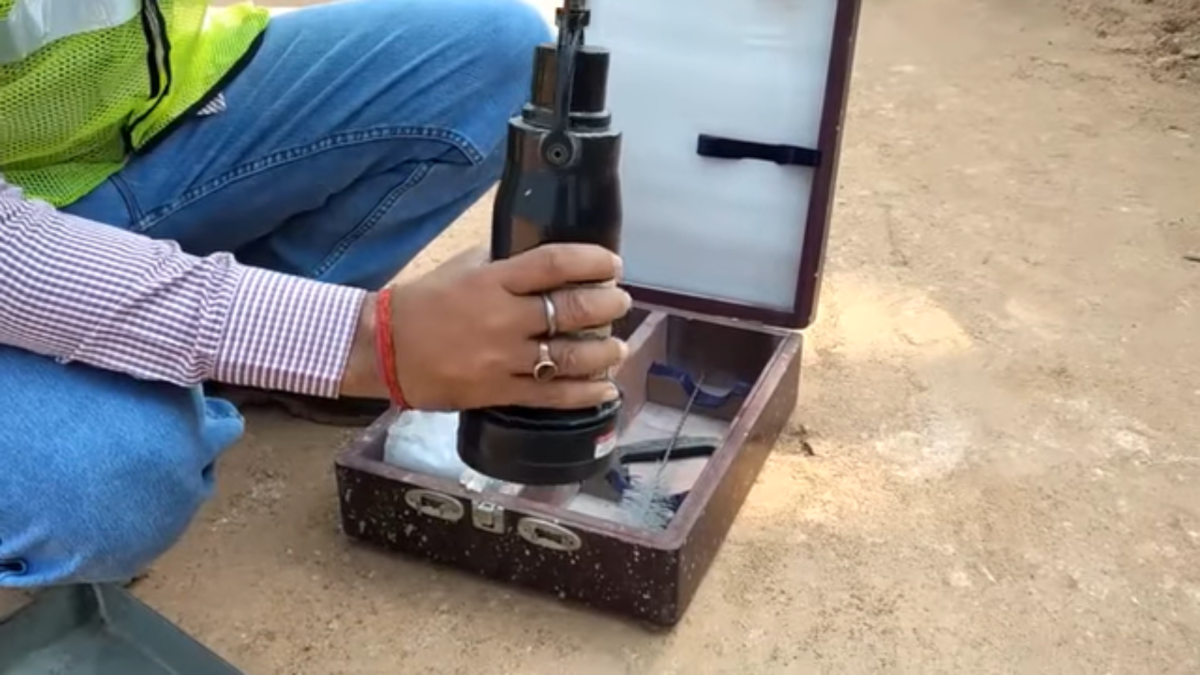
2. Charging of  viscometer -Charge the viscometer by pouring the prepared sample to within ± 2 mm of flll line E. Place the charged viscometer in an oven or bath maintained at 135 ± 5.5°C for a period of 10 ± 2 min to allow large air bubbles to escape.

3.Testing – Maintain the temperature of bath 60˚C ± 0.1°C & keep the charged viscometer vertical in position  into the water. Establish a vacuum of 30 ± 0.05 cm of mercury in the vacuum system and connect it to the viscometer with the valve closed. After the completion of  30 ± 5 min kept in bath , open the valve and allow the asphalt to flow into the viscometer. Measure to within ± 0.5 s the time required for the leading edge of the meniscus to pass between successive pairs of timing marks.

4.Test Completion – After the  completion of the test, remove the viscometer from the bath and place it in an inverted position in an oven maintained at 135 ± 5°C to drained off thoroughly from the viscometer. Clean by rinsing several times with benzine completely.

Calculation

Calculate the viscosity by the following equation:

Viscosity in  Poises = Kt

where K= calibration factor, in poise per second; and t = flow time, in seconds.

Always report the test temperature and vacuum with the viscosity test results. For example, viscosity at 60°C, 30 cm Hg Vacuum in poises.

PRECISION

The second test results of sample should not differ by more than the following:

1. Repeatability 7 % of their mean 

2. Reproducibility 10 % of their mean

Facebooktwitterredditpinterestlinkedinmail

VARIATION IN MOISTURE CONTENT DURING COMPACTION TEST

SCOPE

For the determination of dry density of soil when water is added into the sample of soil , it becomes easier for soil particles to move over another particle after applying external forces or compactive force . Owing to that the soil particles come closer & closer hence voids are reduced ultimately which causes the dry density to increase. As we go on increasing the water content , the soil particles creates larger water films around them.

Owing to that dry density goes on increasing till a stage is reached where water starts occupying the space which have been occupied by the soil particle. At this stage  achieved density is called maximum dry density. For any compacted soil there is certain moisture content at which soil can be compacted at maximum instant.
In MORT&H specification following tolerances has been given while carrying out the compaction test.

1.EMBANKMENT: As per MORT&H 5th Revision compaction requirement is 95% of dry density & moisture requirement is 1% above and 2% below of OMC. For example if OMC is 11% range will be 9 % to 12% •

2.SUBGRADE: As per MORT&H 5th Revision compaction requirement is 97% of dry density & moisture requirement is 1% above and 2% below of OMC. For example if OMC is 11% range will be  9 % to 12% •

3.GRANULAR SUB BASE(GSB): As per MORT&H 5th Revision compaction requirement is 98% of dry density & moisture requirement is 1% to 2% below of OMC. For example if OMC is 11% ; range will be   11 % to 9% •

4.WET MIX MACADAM: As per IRC 109 – 2015 compaction requirement is 100% of dry density & moisture requirement is 2% above and 2% below of OMC. For example if OMC is 11% ; range will be 9% to 13% 0f OMC.

5.CEMENT TREATED BASE & SUBBASE: As per MORT&H 5th Revision compaction requirement is 98 % of dry density & moisture requirement should not be more 2% OMC. For example if OMC is 11% range will be 11 % to 13%.

Reference :

1.MORT&H 5th Revision

2.IRC 109 -2015

Facebooktwitterredditpinterestlinkedinmail

VISCOSITY TEST OF BITUMEN EMULSION BY SAYBOLT VISCOMETER (IS-3117-2004)

Scope:

This test method describes  how to find out the viscosity of bitumen emulsion with Saybolt Furol viscometer. It is applicable to all the emulsified asphalts specified in Specifications IS-3117-2004

Apparatus:

a.Water Bath — Bath equipped with a stirring device and with means for heating or cooling, serves as a support to hold the oil tube in the vertical position and as a container for the bath liquid. 

The bath temperature necessary to maintain thermal equilibrium, while the liquid in the oil tube is swell stirred by the oil-tube thermometer, shall vary to within +/- 0.1˚C , for the specified test temperatures given below:

Temperature Range  19 to 27 ˚ C

Temperature of Test  25˚ C

The level of the bath liquid shall be not lower than 0.5 cm above the overflow rim of the oil tube.

b.Oil Tube Thermometers — Four thermometers graduated in  degree centigrade which can measures the temperature upto 100˚C or self-reading electronic thermometer.

c.Timing Device — A stop-watch graduated in divisions of 0.2 s or less and accurate to within 0.1 percent when tested over a 60 min period; or other equivalent timing device.

d.Withdrawal Tube or Pipette— Used for draining the gallery, with a smooth tip of about 3 mm outside diameter and about 2 mm inside diameter. 

Procedure

1.Make the viscosity determinations in a room free from draughts and rapid changes in temperature.

2.For standardization, the room temperature shall be between 20˚C and 30˚C and the actual temperature shall be recorded & for routine testing , temperatures up to 38°C may prevail without introducing errors in excess of one percent.

3.Clean the oil tube with a solvent, such as benzene, and remove excess solvent from the gallery. Sieve the all sample  through a 150 micron  IS sieve before pouring into the oil tube. Pour the material in oil tube. Insert the cork stopper , taking care that the cork fits tightly enough to  prevent the escape of air, as tested by the absence of oil on the cork after it is withdrawn. If the test temperature is above that of the room, heat the material to not more than 1.5 ˚C above the temperature of test, and if the temperature is below that of the room, cool it to not more than 1.5˚C below the temperature of test.

4.Pour the material into the oil tube until it ceases to overflow into the gallery. Keep it well stirred with the oil tube thermometer, care being taken to avoid touching the outflow tube. Make an adjustment of  bath temperature to remain constant of sample temperature. if the indicated bath temperature varies by more than+/- 0.03˚C test result shall be discarded.

5.After the temperature of the material in the oil tube has remained constant with +/- 0.02°C of the desired temperature for 1 min with constant stirring, withdraw the oil tube thermometer and remove the surplus material from the gallery by the help of the withdrawal tube so that the level of the material in the gallery is below the level in the oil tube proper. 

6.Place the receiving flask in position in such that flask is not less than 10 cm and not more than 10 cm from the bottom of the bath. Remove the cork from its position and at the same time start the stop watch &  Stop the stoop watch  when liquid reaches the  designated mark of the receiving flask.

Reporting Results

1.Note the time in second as determined from above said procedure & it will be the Saybolt Furol Viscosity of the material at the temperature at which the test is made.

2.Report the results to the nearest 0.1 s for viscosity values below 200 second and to the nearest whole second for values 200 second or above.

Reproducibility Of Results

With proper attention to details of method of procedure, results indifferent laboratories with different operations under referee conditions of testing shall not differ by more than 0.5 percent.For more detail please my video in youtube.

Facebooktwitterredditpinterestlinkedinmail

COMPRESSIVE STRENGTH TEST OF CEMENT MORTAR CUBE AS PER IS 4031 PART 6

1.SCOPE

1.1 This standard IS 4031  ( Part 6 ) covers the procedure of finding out compressive strength of cement: The strength of cement is determined by compressive strength tests, on 70.6 mm mortar cubes, made with specified cement , sand & water mixed & compacted manually with a compacting bar  as well as with vibrating machine.

 2. SAMPLING AND SELECTION OF TEST SPECIMEN

2.1 . The representative sample of the cement selected as above shall be thoroughly mixed before testing requirements of different equipment used for testing of cement. 

3. TEMPERATURE AND HUMIDITY

 3.1 The temperature of the testing room, dry material ingredient and water should be maintained at 27 ± 2°C & relative humidity of the chamber or room should be maintained at 65 ± 5 percent.

 3.2 The curing tank or box temperature & relative humidity should be maintained at 27 ± 2°C and more than 90 percent respectively

4. GENERAL

 4.1 Standard Sand.- The standard sand which is to be used in the test shall confirm to IS: 650 -1966·

5. APPARATUS

5.1 Vibration Machine – Vibration machine conforming to IS : 10080-1982.

 5.2 Poking Rod – Poking rod conforming to IS: 10080-1982.

5.3 Cube Mould- The. mould should have a size of 70.6 mm x 70.6 mm x 70.6 size conforming to IS : 10080-1982.

 5.4 Gauging Trowel – Gauging trowel  having steel blade 100 to 150 mm in length with straight edges weighing 210 ± 10 g.

 5.5 Balance – Electronic balance with 1 gm accuracy shall be used.

5.6 Graduated Glass Cylinders – Graduated glass cylinders with capacity of 150 to 200 ml .

6. PREPARATION OF TEST SPECIMENS

6.1 Mix Proportions and Mixing

6.1.1 The temperature of water & test room at the time of mixing operations shall be maintained at 27 ± 2°C. Use Potable water for preparing the cubes.

 6.1.2 The cement , standard sand & water for each cube shall be taken as per below mentioned standard :

a.Cement 200 g

b.Standard Sand 600 g ( 200 gm of each grading)

c.Water ( P/4+ 3.0) percent of combined mass of cement and sand, where P is the normal consistency of cement.

If normal consistency of cement  is 29.5 (assumed)  calculation of water will be done as below:

( P/4+ 3.0) x  1/100 x 800 = ( 29.5/4+ 3.0) x 1/100 x 800 = 83 gram.

6.1.3 Place on a nonporous plate, a mixture of cement and standard sand, Mix it dry with a trowel for one minute and then with water until’ the mixture is of uniform colour. The quantity of water shall be used as calculated from above equation. The mixing time shall  be in between 3  to 4 minutes, the mixture shall be rejected  if the time is less than 3 minutes and more than 4 minutes and the operation should be repeated with a fresh quantity of cement, sand and water.

6.2 Moulding Specimens

 6.2.1 In assembling the moulds ready for use, the sides of the mould shall be made from ferrous metal. All parts shall be robust enough to prevent distortion & the joints between the sides of the mould and between the sides and the base plate shall be  coated with oil or grease to prevent leakage of water from mould .

6.2.2 Place the assembled mould on the vibrating table machine vibration by proper holding in position by suitable clamp  & shall not be removed until the completion of the vibration period.

 6.2.3 Immediately after mixing the mortar properly , place the mortar in the cube mould and rodded with the rod specified rod. The mortar shall be rodded 20 times in about 8 second to eliminate entrained air . Pour the remaining quantity of  cement mortar into the hopper of the cube mould and rodded again as done previously for the first layer and then compact the mortar by vibration.

6.2.4 Keep the period of vibration 2 minutes at the  speed of 12000 ± 400 vibration per minute.

6.2.5 After the end of vibration, remove the mould with base plate from the machine and make proper smooth finish top surface of the cube mould with the blade of a trowel.

 6.3 Curing of Specimen

Keep the prepared cube mould filled in moist closet or moist room or curing tank  for 24 hours . After completion of 24 hours , remove the mould form cube and immediately keep in clean fresh water . The water in which the cubes are kept shall be changed after every 7 days and keep on maintaining temperature 27 ± 2°C.

7. Testing

 7.1 Take out the three test cubes each for 3 , 7 & 28 days respectively for testing of  compressive strength  after completion of test age  for different cements.

7.1.1 Place the test cube in center of cube testing machine without any packing and apply the load steadily and uniformly , starting from zero at a rate of 35 N/mm²/min.

8. Calculation

8.1 Calculate compressive strength of cement by dividing the maximum load applied to the cubes during the test by the cross-sectional area, calculated from the mean dimensions of the section and shall be expressed to the nearest 0.5 N/mm².For more detail see my video in you tube.

Facebooktwitterredditpinterestlinkedinmail