1.0 Scope
2.0 General
3.0 Materials
4.0 Procedure
5.0 Precaution
6.0 Opening to traffic
1.0 Scope
The work shall consist of providing and laying of pavement marking with hot applied thermoplastic paints (type-2) as per Clause 803 of MORT&H.
2.0 General
This method statement covers providing and laying of pavement marking with hot applied thermoplastic paints as Per IRC: 35 code of practice for road marking and specified in drawing of as directed by the Engineer.
3.0 Materials
Materials of road marking shall be hot applied thermoplastic compound and the same shall meet the requirements as specified in clause 803.2 of MORT&H.
Composition: The pigment, beads, and aggregate shall be uniformly dispersed in the resin. The material shall be free from all skins, dirt and foreign objects and shall comply with requirements indicated following table.
Proportions of constituents of Material (% by weight)
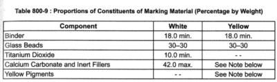
Note: Amount of calcium carbonate and inert fillers shall be at the option of the manufacturer, provided all other requirements of this specification are met.
3.1 Properties: The properties of thermoplastic material, when tested in accordance with ASTM D36/BS-3262-(Part I) shall be as below;
a. Luminance :
b. White: Daylight luminance at 45 degrees – 65 percent min as per AASHTOM 249.
c. Drying time: when applied at a temperature specified by the manufacturer and to the required thickness, the material shall set to bear traffic in not more than 15 minutes.
d. Skid resistance: not less than 45 as per BS 6044.
e. Cracking resistance at low temperature: The material shall show no cracks on application to concrete blocks.
f. Softening point: 102.5+/- 9.5ºC as per ASTM D 36.
g. Flow resistance: Not more than 25 per cent as per AASHTO M 249.
h. Yellowness index (for white thermoplastic paint: not more than 0.12 as per AASHTO M 249.
i. Storage life: The material shall meet the requirements of these specifications for a period of one year. The thermoplastic material must also melt uniformly with no evidence of skins or un-melted particles for the one year storage period. Any material not meeting the above requirements shall be replaced by the manufacture/supplier/Contractor.
j. Reflectorisation : shall be achieved by incorporation of beads, the grading and other properties of the beads shall be as specified in clause 803.4.3 of MSRT&H.
3.2 Marking: each container of the thermoplastic material shall be clearly and indelibly marked with following information.
The name, trade mark or other means of identification of manufacturer.
Batch number
Date of manufacture.
Colour (white or yellow)
Maximum application temperature and maximum safe heating temperature.
3.3 Sampling and Testing: The thermoplastic material shall be sampled and tested in accordance with the appropriate ASTM/BS method. The Contractor shall furnish to the Employer a copy of certified test reports from the manufacturer of the thermoplastic material showing results of all tests specified herein and shall certify that the material meets all requirements of this specification
3.3.1 Reflective glass beads
The glass beads shall be transparent, Colourless and free from milkiness, dark particles and excessive air inclusions. These shall conform to the requirements spelt out in Clause 803.4.2.3 of MORT&H.
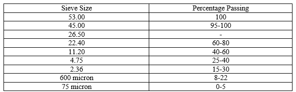
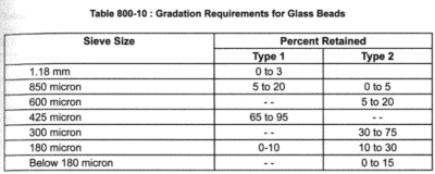
Gradation: The glass beads shall meet the graduation requirements for the two types as given in the following table Table 800-10
Roundness: The glass beads shall have a minimum of 70 per cent true spheres
Refractive index: The glass beads shall have a minimum refractive index of 1.50.
Free flowing properties: The glass beads shall be free of hard lumps and clusters and shall dispense readily under any condition suitable for paint stripping. They shall pass the free – Flow test.
Before taking up of laying markings, program for the diversion of traffic shall be drawn up and got it approved by the Engineers as per 112 of MOSRT&H and as per IRC: SP-55.
Temporary sign boards, barricading, flags, lights and flagmen will be provided at working area as per approval of the Engineer.
On both sides, suitable regulatory/warning signs as approved by the Engineer shall be installed for the guidance or roads users.
4.0 Procedure
4.1 Equipment to be used
- Pre-Melter
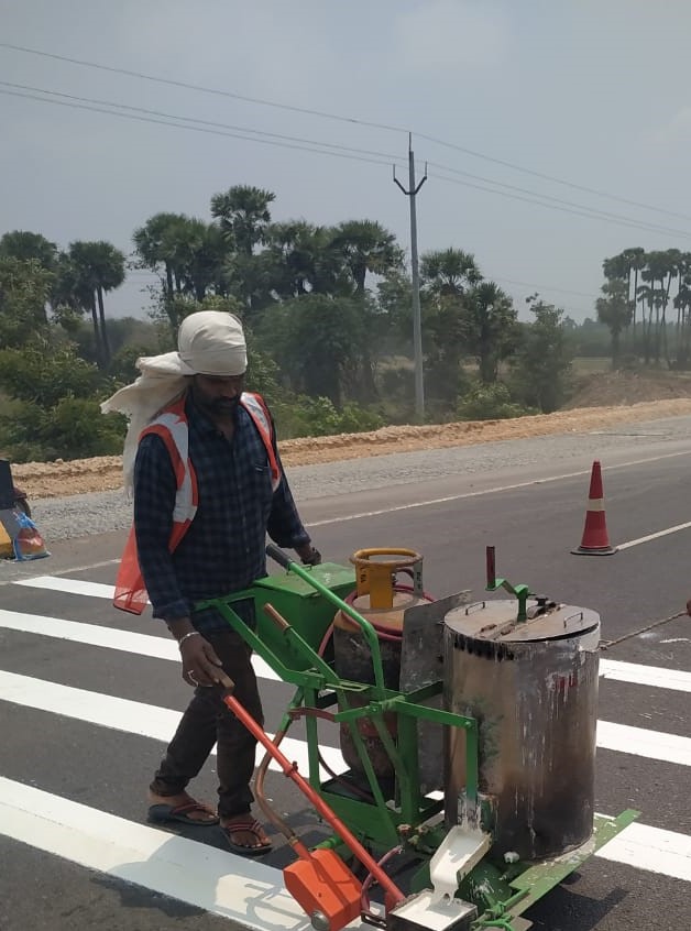
- Pram-applicator
- Mechanical Broom
- Air compressor
- Truck
- Water tanker with pipe attachment
- Survey kit / instrument
4.2 Construction operation
4.2.1 Preparation (as per MORT&H Clause:803.4.4):
The material shall be melted in accordance with the manufacturer’s instructions in a heater fitted with a mechanical stirrer to give a smooth consistency to the thermoplastic material to avoid local overheating. The temperature of the mass shall be within the range specified by the manufacturer, and shall on no account be allowed to exceed the maximum temperature stated by the manufacturer. The molten material should be used as expeditiously as possible and for thermoplastic material which has natural binders or is otherwise sensitive to prolonged heating the material shall not be maintained in a molten condition for more than 4 hours.
After transfer to the laying equipment, the material shall be maintained within the temperature range specified by the manufacture for achieving the desired consistency for laying.
4.2.2 Cleaning: The surface of the flexible road pavement shall be thoroughly cleaned form all of dust any other material, grease, oil etc. at the area where the material shall be applied to mark the pavement with the help of broom and air compressor.
4.2.3 Pre- Marking: The reference centre – line ( Pre-Marking) of the lane marking as per the drawing shall be made to have temporary marking with chalk powder/long thin rope ,so that the applicator machine pointer in the front of the machine can be guided to move along this pre-Marked line while material is being applied on the road . This ensures accurate alignment of the markings when laid on the road surface.
4.2.4 Heating of the Material: The material shall be heated in the pre-Melter as well as pram-applicator machine fitted with mechanical stirrer to give smooth consistency to the material and to avoid local heating of the material. For heating, LPG with suitable burner system shall be used to achieve temperature of 180+/-10º C which is the specified application temperature. The temperature Gauge fitted on the machine as well as the pre-Melter displays the material temperatures continuously for monitoring the application temperature.
4.2.5 Lane Markings: The lane marking shall be made as per the approved drawing for width; length and thickness shall be made with the help of the Screed- Box attached to the Applicator Machine. The thermoplastic paint shall be applied in intermittent of continuous lines of uniform thickens of at least 2.5 mm. where arrows or letters are to be provided. Thermoplastic compound may be hand sprayed. The tolerances of the width, position alignment and length of segment of broken lines shall be as per Technical specification sub clause 803.6.6.
4.2.6 Drop-On Glass Beads Application: The approved glass beads shall be placed in position from the bead dispenser attached to the machine and the dispersion is by forced –feed mechanism which works while the machine is applying the markings with the screed –Box., simultaneously and before the thermo plastic material (which is hot applied) becomes dry and cold while achieving road surface temperature. The type-2 glass beads conforming to the above noted specification shall be sprayed uniformly into a mono-layer on to the paint line at the rate of 250 grams per square meter area.
5.Precaution:
1.The strip shall not be slippery when wet.
2 .The marking shall not lift from the pavement in freezing weather.
3.After application and proper drying, the stripe shall shown no appreciable deformation or discoloration under traffic and under road temperatures up to 60º C.
4.The marking shall not deteriorate by contact with sodium chloride or oil drippings from traffic.
5.The stripe or marking shall maintain its original dimension and position. Cold ductility of the material shall be such as to permit normal movement with surface without chopping or cracking.
6.The marking shall be done with approved Material ONLY on dry pavement surfaces of minimum Temperature of 10º C.
7.The arrow marking shall be made using the approved material with specifically made stencils of shape and size.
6.Opening to traffic: Traffic will be opened after 24 hours.