Methods Statement Ultrasonic Pulse Velocity Testing

Introduction : This test is done to assess the quality of concrete ,this method consists of measuring the time of travel of an ultrasonic pulse passing through the concrete being tested. Comparatively higher velocity is obtained when concrete quality is good in terms of density, uniformity, homogeneity etc. There are mainly two transmission methods ,  direct and indirect . In direct transmission method of ultrasonic pulse velocity is passes on opposite faces directly(both faces)  but in the indirect transmission method  transmission arrangement is placed on same faces .This is least sensitive and shall be used when only one face of the concrete is accessible, or when the quality of the surface concrete relative to the overall quality is of interest. If the transducers and receiver has been placed in same side it will be called Surface probing . Indirect velocity is invariably lower than the direct velocity on the same concrete element. This difference may vary from 5 to 20 percent depending largely on the quality of the concrete under test. For good quality concrete, a difference of about 0.5 km/s may generally be encountered. For the procedure and for calculating the exact value of ultrasonic pulse velocity by surface probing. it is recommended by the code IS 516 (Part 5/Sec 1) : 2018 while using  surface probing method the pulse velocity may be increased by 0.5

Reference code & Method : IS 516 (Part 5/Sec 1) : 2018 , Surface probing & Direct

Procedure :  We will use surface probing method due to one face accessible (Indirect Velocity).

1.At the point of observation, the concrete surface shall be suitably prepared and any plaster or other coating shall be removed to expose the concrete surface. For this purpose, the use of carborundum stones or grinders may be adopted. However, care shall be taken to avoid any damage to concrete surface or concrete structure.

  1. Before switching on the ‘V’ meter, the transducers should be connected to the sockets marked “TRAN” and ” REC”.
    The ‘V’ meter may be operated with either:
    a) the internal battery,
    b) an external battery or
    c) the A.C line.

3 . A reference bar is provided to check the instrument zero. The pulse time for the bar is engraved on it. Apply a smear of grease to the transducer faces before placing it on the opposite ends of the bar. Adjust the ‘SET REF’ control until the reference bar transit time is obtained on the instrument read-out.

  1. Place the two transducers on opposite faces (direct transmission), or on adjacent faces (semi-direct transmission), or on the same face (indirect or surface transmission) . For maximum accuracy, it is recommended that the 0.1 microsecond range be selected for path length upto 400mm

5.Having determined the most suitable test points on the material to be tested, make careful measurement of the path length ‘L’. Apply grease to the surfaces of the transducers and press it hard onto the surface of the material. Do not move the transducers while a reading is being taken, as this can generate noise signals and errors in measurements. Continue holding the transducers onto the surface of the material until a consistent reading appears on the display, which is the time in microsecond for the ultrasonic pulse to travel the distance ‘L’. The mean value of the display readings should be taken when the units digit hunts between two value. Calculate the pulse velocity by using following formula

Pulse velocity=(Path length/Travel time)

Reporting the Result : While reporting the result surface probing system should be considered.

Precaution : Prevent the two transducer leads from coming into close contact with each other when the transit time measurements are being taken. If this is not done, the receiver lead might pick-up unwanted signals from the transmitter lead and this would result in an incorrect display of the transit time.

Facebooktwitterredditpinterestlinkedinmail

METHOD STATEMENT FOR BRIDGE LOAD TEST

  1. Purpose

Purpose of this test is too serve the behavior of the bridge by the application of design live load or load slightly exceeding design live load over a long period of 24 hours and elastic performance of bridge deck on removal of test load. It is used to assess the condition and safety of bridge. The load testing is used to check whether maximum deflection and percentage recovery are within permissible limits or not.

  1. Relevant code

Bridge Load Test shall be conducted as per guideline provided in IRC: SP: 51-2015.

3. Scope & Provided by Sponsor

Scope of work includes conducting the Span Load Test.

a) Span Length             –                        As per drawing

b) Test Span                 –                         As per drawing

c) Width of Carriage way –                As per drawing

d)Test Load                  –                         As per drawing

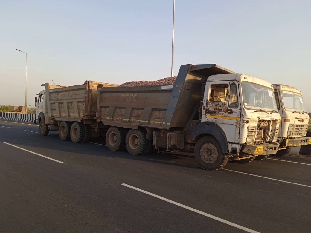
Method of Loading         –         By filling suitable material in truck.

e) Location of Dial Gauge At L/4, L/2 and 3L/4 of the bottom side of girder.

(where L is the c/c distance between the bearing) as indicated in or as specified in Drawing

f) Dial Gauge to be installed for Test Span– 3 nos. Dial Gauge on one girder as mentioned in drawing.

g) Nos. of Dial Gauge to be installed for Bearings settlement – 2 nos. or as mentioned in drawing.

4. Test Set-up for Span Load Test

a. Deck shall be cleaned properly; white wash shall be applied at the critical section on Girders. Deck shall be marked for the loading area as per drawing.

b. Trucks loaded with suitable material like aggregate, sand, cement bags etc.

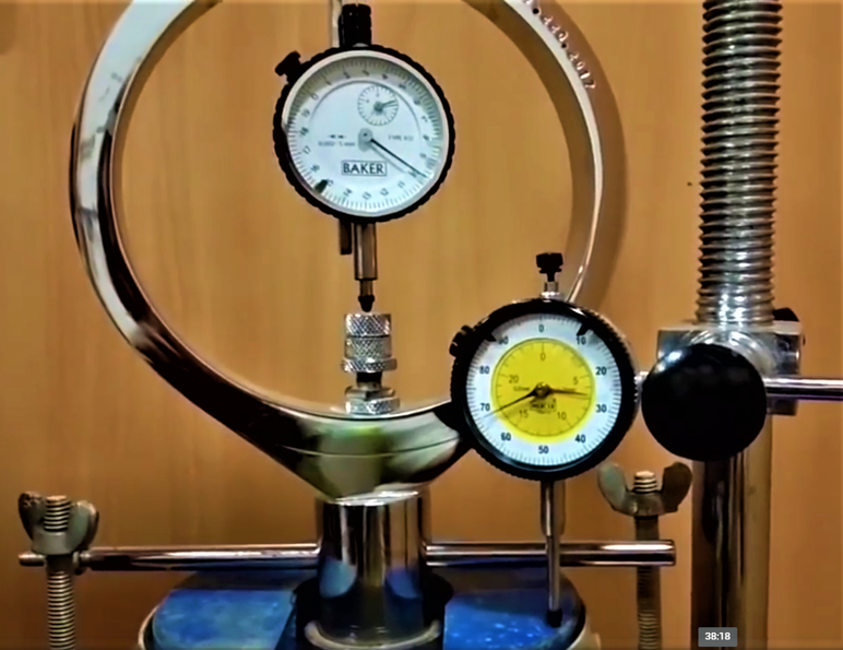
c. Deflection of girder shall be measured by Dial Gauge of 0.1 mm least count which detect the Dial Gauge which are fixed on bottom side of girder.

d. Wherever Dial Gauge cannot be fixed on bottom side of girder due to water flow under bridge. Then total station and Dial Gauge should be used on top of deck slab of bridge. Point of Dial Gauge should be marked on top of deck slab at distance of L/4, L/2 and 3L/4 or distance given in drawing according to alignment of girder.

5.PROCEDURE OF LOAD TESTING

 1) The test will be carried out as per IRC SP 51 -2015 Instruments assembled at desired location such as, Dial Gauge, Strain Gauges & Digital Thermometer

 2) Visual inspection of bridge is done. In Visual Inspection, Bearing and expansion joints will be checked. Both must be in their functional and working condition. The traffic will be closed for further testing and whitewash is applied to the superstructure for monitoring of cracks.

3) Dial Gauges will be placed on magnetic stands. Dial Gauges will be placed firm on scaffolding platforms with steel plates, so that magnetic stands are firmly located. Dial gauges were mounted just by touching the soffit of structure.

 4) Glass plate of size 50x50x5 mm shall be fixed to structure at location of Dial Gauges for positioning.

 5) Before loading the precautions should be taken.

a) All staging provided shall be stable and safe.

b) Staging for instruments and observers shall be independent.

c) Staging for instruments shall be rigid.

6) As per IRC SP 51, Loading Operation Stages from 50%, 75%, 90%, 100% of test load in 4 stages, which shall be completed in 4 hrs. At the starting of Bridge load test 50 % of load on bridge is taken, out of total  50%  then 75%  then 90%  & 100% . We had to increment the load at the interval of every 1 hour during this the deflection will be recorded at each stage of loading.

7) After completing loading, we had to keep it retained for 24 hrs and observe.

8) After 24 hours, Structure shall be unloaded at same stage of loading i.e. 100% , 90% , 75% , 50% & 0%. But unloading shall be done in same way of loading , load shall be removed at 1 hour of interval from 100% to 90% to 75% to 50%  to 0%  as well as deflection is rewarded at each stage.

9) Measurements will be recorded at every hour of loading and unloading.

10) Data will be collected by visual observation before and after loading and there will be interpretation of results

  1. OBSERVATION

The following observation shall be made before/during/after testing

i) Deflection at critical section

ii) Appearance of crack and their development, length and location

iii) Deformation of bearing

iv) Ambient temperature and relative temperature of the body in the structure

  1. Temperature Measurement

Temperature of any component like pier, abutment wall of the bridge will be monitored at every one hour or as per drawing. For structure temperature, drill a hole and put digital thermometer in hole at any one point. Also environmental temperature should be recorded.  The measurement will be taken by the digital thermometer. Reading of Dial Gauge point at every one hour or as per drawing should be note down for 24 hours. The reading of temperature will be used in temperature correction factor.

Facebooktwitterredditpinterestlinkedinmail

PROCEDURE FOR QUALITY RECORDS

Quality records testifying to the satisfactory execution of project activities and quality objectives shall be legible, specify the work involved, properly maintained, readily retrievable, and available to authorized personnel.

In this procedure , we shall discuss in details pertaining to generating and maintaining the Quality Records for or by the construction.

1.GENERAL

Quality Records are documented evidence that construction conformed to requirements of contract as well as  design specifications.  Quality Records include:

  • Test and inspection reports
  • Monthly Reports
  • Material and equipment certificates required by specification
  • Equipment maintenance/preservation records
  • Acceptance and test data results
  •  Non conformance’s
  • Corrective action ordered/taken
  • Audit reports
  • Project activity
  •  Amount and type of material used
  • Frequency and accountability of submissions

Specified construction staff are liable for the preparation and maintenance of Quality Records. All records are identified as “Confidential”  in accordance with specific procedures established by contract agreement.

2.PROCEDURE

  • Site Quality Manager

In coordination with the Site Execution Manager or the other group manager who receives or generates quality records, identify the quality records that will be retained during construction and identify the record custodian by job title.

 In coordination with the client and other record custodians, define the Quality Records that are to be submitted to the client after completion of specified work or activity and identify this on the Standard Quality Records Control form.

The Site Quality Manager in coordination with the Site Manager will identify all Quality Records (or copies of records) that will be retained in the Records Retention center. Identify this on the Quality Control Records form.

Maintain all the Quality control Records form current and, if possible, before records are received on site or generated.

a.Custodian

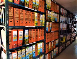
Establish and maintain a file system for inspection, testing, and l Quality Control records system.  The system shall ensure that records are easily available and protected.The system is to be identified on the Quality Records Control Form.

 Before filing the record the custodian shall review the documents to verify the following:

  • Documents are appropriate
  • Documents are complete
  • Entries are correct – Documents are legible
  • Documents signed by authorized person

The custodian review the document with the originator or originator’s supervisor.  Resolve any discrepancies with vendor documents through the purchasing department.

If any corrections required in the records to be accomplished by authorized personnel (i.e. record originator or originator’s supervisor) by entering the correct information and dating the change.

b.Turnover

Maintain the records until they are requested by project turnover and/or assigned to the Records Retention Center.

The Site Quality Manager will generate a checklist and verify that all required quality records have been completed and those designated for turnover are included in the Turnover Package.

All supporting documentation relating to completion will be retained by organization until system acceptance by Client.  After system acceptance by Client, this documentation will be transferred to Client under separate correspondence.

Facebooktwitterredditpinterestlinkedinmail

DOCUMENT CONTROLLING PROCEDURE

Documentation relating to all project activity is prepared and maintained by
each organizational element. Such documentation will provide accurate and
current information on all project activities and for all information which contributes to the understanding of the project. Records are reviewed by appropriate personnel and provided to all concerned organizational elements. Procedure for documentation and record maintenance and retention are given as below:

1. SUMMARY
1.1. This procedure defines the requirements for the creation, review, approval, distribution, use and revision of quality management system documents.
1.2. This procedure applies only to documents which instruct office/site staff on how to carry out activities and tasks; this includes manuals, procedures, forms and instructional sheets or posters.
2. PROCEDURE
2.1. Creation of Documents
2.1.1. Documents are created by an appropriate subject matter expert.
2.1.2. All internal documents are created as soft files (MS Word®, etc.); it is recommended that files of a similar type follow the format of other documents in that type.
2.1.3. Draft versions must then be sent to the appropriate approver(s) for review and approval.
2.1.4. Original releases of documents are given a revision indicator of “0”.
2.2. Review and Approval
2.2.1. The Quality Manual may only be approved by the senior Management. Other documents are to be approved by the original author, or a company executive.
2.2.2. Draft files may be sent to the approver(s) via hard copy or e-mail.
2.2.3. The reviewer will resolve any issues with the original author to achieve a satisfactory document.
2.2.4. The reviewer will indicate approval of the document by e-mail.
2.2.5. The approved document shall then be forwarded to the Document Controller .
2.2.6. If hard copy binder will be used , document Controller , will maintain a binder of most current hard copy versions of documents.
2.2.7. The Document Controller will maintain a computer folder, on the company server, for the latest soft copy versions of document with backup facility. The Document Controller Title will place new or revised documents into that folder, Any previous soft versions are then moved to a separate folder identified for obsolete documents which are kept for historical purposes.
2.2.8. The directory of official released documents shall act as a “master list” of documents, indicating the setting each file’s permission to READ ONLY, or converting the released versions to a non-editable file format.
2.2.9. current versions of all documents. No other master list is required.
2.3. Distribution of Documents
2.3.1. If intranet is used, Controlled documents will be available via the intranet for all employees.
2.3.2. If hardcopy document distribution is used, the Document Controller will maintain a list of where controlled hardcopy documents are to be distributed. The Document Controller will be responsible for distributing updated copies of such controlled hardcopies to proper locations. Controlled hardcopies shall be marked with stamp in color ink on the first page as CONTROLLED, to distinguish them from uncontrolled documents or photocopies.
2.3.3. Controlled hardcopies may not be altered or modified by users, and must remain legible and readily identifiable. This includes hand mark-ups by unauthorized personnel. Controlled hardcopies may not be photocopied, unless for the purposes of sending to a recipient who is authorized to receive uncontrolled versions of Project documents (i.e., a vendor or customer).
2.4. Re-Evaluation
2.4.1. Documents must be reviewed by the original author or another subject matter expert or top manager as required.
2.4.2. The Document Controller will ensure re-evaluation is conducted and that documents are updated if required. The Document Controller will maintain a record of document re-evaluations of any process, to identify when documents are due for re-evaluation.
2.4.3. If a document is determined to require updating, the changes shall be made and a new version issued per the rules below.
2.4.4. If a document is determined not to require updating, no action on the document is necessary.
2.5. Revising Documents
2.5.1. Changes to documents go through the same steps as original issue, except that their revision level is advanced upon approval.
2.5.2. Only authorized personnel may change documents, although any employee can request a change to their Manager, or other document change request form. All the revised document shall include a change history table within its text.
2.5.3. Any changes to documents require authority review and approval shall be submitted accordingly, and not implemented until such approval is obtained.
2.5.4. If document changes require regulatory approval prior to implementation, this will be obtained in writing & reflect the reason for the change.
2.5.5. Re-evaluation, inspection (where applicable) and internal auditing will confirm the effectiveness of changes.
2.6. Controlling Documents of External Origin
2.6.1. For external documents such as standards or third party specifications which are referenced in a customer purchase order or contract, these documents may be maintained without control.
2.6.2. For external documents such as standards or third party specifications which are not referenced in a customer purchase order or contract, these must be controlled. Such control requires that the Document Controller or responsible manager obtain the latest version of the document, and maintain it on the company server (for electronic versions) or in a binder of controlled external documents (for hardcopies). Like other controlled documents, these may not be edited or copied.
2.6.3. Third party specifications and prints, including those of the customer, are controlled per the configuration management requirements set forth in the Quality Manual .
2.6.4. External documents for non-critical use, such as user manuals, reference books, marketing materials, and supplier directories are not controlled.
2.7. Forms
2.7.1. Forms are a special kind of document that may be photocopied as needed. A softcopy of each approved form should be sent to document controller for his record for inclusion in the Document Master List .

Facebooktwitterredditpinterestlinkedinmail

Calibration Procedure Of Equipment

  1. SUMMARY
    • The aim of this procedure is to define the necessity for calibration or verification of equipment which can be used to determine the acceptability of product.
    • The QA/QC Head will be responsible for implementation and management of this procedure.
  1. PROCEDURE: CALIBRATION
    • Devices subject to calibration shall be calibrated by an approved outside service provider, or by trained employees.
    • Third party calibration laboratories should be accredited to NABL whenever possible, as this provides the best control of calibration activities, and traceability to national standards.
    • When staff perform in-house calibration, this shall be performed in accordance with documented procedures for each & every type of calibration performed.
    • Traceability to the national standards should be maintained for all devices where such traceability is possible .
    • Approved calibration service providers should maintain suitable environmental conditions for calibration such as temperature and relative humidity on any calibration test certificates. For in-house calibration, the QA/QC head will ensure suitable conditions for calibration.
    • The Calibration log will be maintained by the QA/QC Engineer. This document will contain the list & make of all devices with serial number, date of last calibration, and next calibration due date. All calibrated certificates must have the identification of any standards used by the calibration house, and their serial numbers, allowing for traceability to Client/ Independent Engineer.
    • For tools calibrated in-house by EPC contractor staff, the results and standards used shall be recorded on the Calibration Record and shall include any standards and/or procedures uses.
    • Calibrated devices should contain a calibration sticker that includes the current calibration status, calibration due date, and device identification number. Where the device cannot accommodate a calibration sticker due to size or frequency of use, the device shall be numbered and the QC Manager shall keep a log of those devices and their status.
    • QC Manager shall submit expired tools to QC Head for recalibration, and he shall positively recall such expired tools for recalibration.
    • An “amnesty window” of 1 week is allowed beyond the due date marked on the device, to accommodate arrangement of calibration or verification, or for production capacity purposes.
    • Devices in use for noncritical measurements are to be marked REFERENCE ONLY.
    • Any device failing to satisfy calibration standards will immediately be taken out of service. The device may then be sent out for repair. Repaired devices must be calibrated before being returned to service.
    • When a measuring device is found to be out of tolerance, and/or reported on the calibration certificate of having been found as “defective” or “out of tolerance” by the third party provider, QC Manager shall be notified immediately. The QC Head shall oversee a study to find out the impact of the out-of-tolerance device on product shipped.
  2. VERIFICATION
    • Where a device cannot be calibrated against traceable standards, it must be verified against some known-good object or method and proven as acceptable.
    • Known-good objects must be protected so their status is not altered, either by physical damage or deterioration.
    • Known-good methods must be documented in procedures, with a rationale for their acceptability being documented.

Facebooktwitterredditpinterestlinkedinmail

DESIGN CONTROL PROCEDURE

1.SCOPE: This procedure identifies design processes that require process control.

2.SUMMARY: The design control is essentially intended for controlling all activities of design planning, design preparation, verification , review and validation so that the final product meet specified requirements .

3.DIFFERENT STAGES OF DESIGN : Following activities covering the different stages of the project:

  • Traffic Survey
  • Inventory and Condition Survey Of Road , Bridges and Culverts
  • Topographic Survey
  • Axle Load Survey
  • Benkleman Beam Deflection Test , If Required.
  • Soil and Material Investigation.
  • Geo-Technical and Sub Soil Investing.
  • Checking , Approval and Filling of Calculation.
  • Review , Approval , checking & verification of Design Outputs.
  • Control of design changes and validation of design.

4.PROCEDURE :

  1. All the activities of project design has been undertaken by ………authorized consultant.
  2. After going through all the procedure above mentioned, the design consultant will submit the design report to the concessionaire.
  3. Concessionaire shall review the design for the suitability & project specific requirement.
  4. If found suitable, analyse the cost calculation and time frame to complete the project in stipulated time frame.
  5. After approval from the management, concessionaire shall submit the design to independent consultant for the review and necessary suggestion.
  6. After review, concessionaire will see the feasibility, if found suitable implement the same for the project.
  7. During execution ,from time to time, keep an eye over the design for practical feasibility, if not matching with the site condition , go for the revision & repeat the process mentioned above.


Facebooktwitterredditpinterestlinkedinmail

Contract Review Procedure

1. Summary
1.1. This procedure defines the process and methods of reviewing contract , and for verifying the project which meets the requirements.
1.2.The contract department is responsible for implementation and management of review activities.

2. Procedure
2.1.Once the contract has been awarded, the Estimating Department generates a “Contract and Specification Review” form which contain the following:
• The contract
• Specifications
• Specific documents and requirements related to production
• General notes
• Project specific work instructions & Circular
• Requirements from the contract or specification that vary will be highlighted, and copies of that will be distributed to the appropriate processing departments.
• Once the designated departments have reviewed the documents, they will sign in the appropriate space, commenting if desired, and return to the QS department. A completed “Contract and Specification Review” sign-off form will demonstrate a complete review.
2.2. Throughout the project, revisions to contract documents will be reviewed with the original Estimate and the Project Coordinator will ensure compliance with the contract documents. The potential cost and/or schedule impacts to the project will be determined based on any changes.
2.3. These subsequent reviews are documented by memo or other suitable means and are routed with a new generated form to any function that is affected by the change to inform and solicit input. The final result’s filed within the job folder.
2.4. The QS department will attach the completed form to the Estimator’s budget sheet(s) and place them in the job folder. The job folder is then furnished to the Project Coordinator for project assignment.
2.5. The Project Coordinator/Vertical head will assign a Job Number to the project and make four copies of the form and re-distribute to all functions.

Facebooktwitterredditpinterestlinkedinmail