1.0 Purpose
This provides details of Method Statement to be adopted for CTSB/CTB laying and compaction. For the functional requirement, the thickness of cement treated bases shall not be less than 100 mm.
2.0 Scope
This work shall consist of mixing, laying and compacting of aggregates mixed with cement in a mixing plant as a sub-base/base course on prepared subgrade/sub-base in accordance with the requirements of the Specifications and in conformity with the lines, grades and cross-sections shown on the drawings or as directed by the Engineer.
3.0 Equipment
Mixing Plant
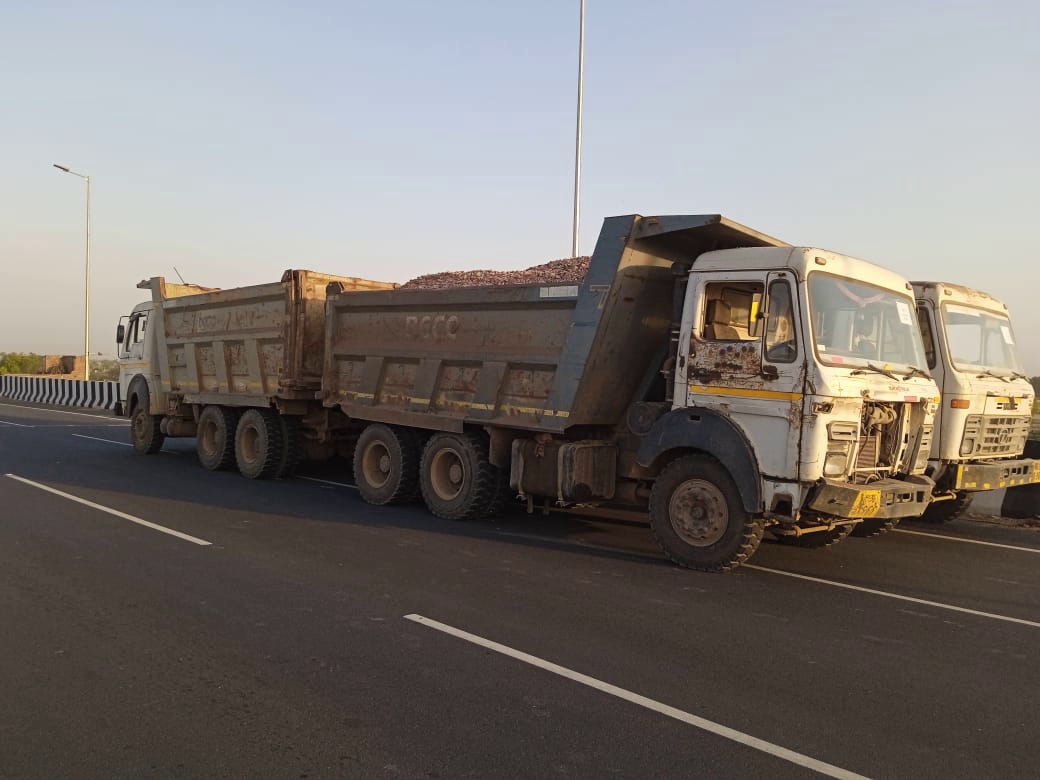
Dumpers/Tippers
Water Tanker
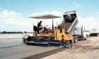
Paver
Roller
4.0 Mix Design
The aggregate gradation for CTB shall be as given in table 400-4 of MORT&H specification. The CTB material shall have a compressive strength of 4.5 MPa in 7 days. The minimum cement content for the mix shall be 2%. Mix shall be got approved by the engineer prior to its use.
5.0 Trial
A minimum 100-meter length of the new carriageway trial patch shall be laid with using hydraulic mechanical pave finisher. Loose thickness of the layer, number of passes of vibratory roller to achieve 98 % modified proctor density, allowance for evaporation of moisture content, and line, level & cross fall shall be established during the trial. Before commencement of main work, trial patch should be got approved from the IE as per their satisfaction.
6. Responsibility
- Section In charge will be responsible for quality control of the section for the construction CTSB/CTB. He will liaise with the Concessionaire Engineer In charge. Further he will be assisted by field engineers, surveyors, supervisors and lab technicians
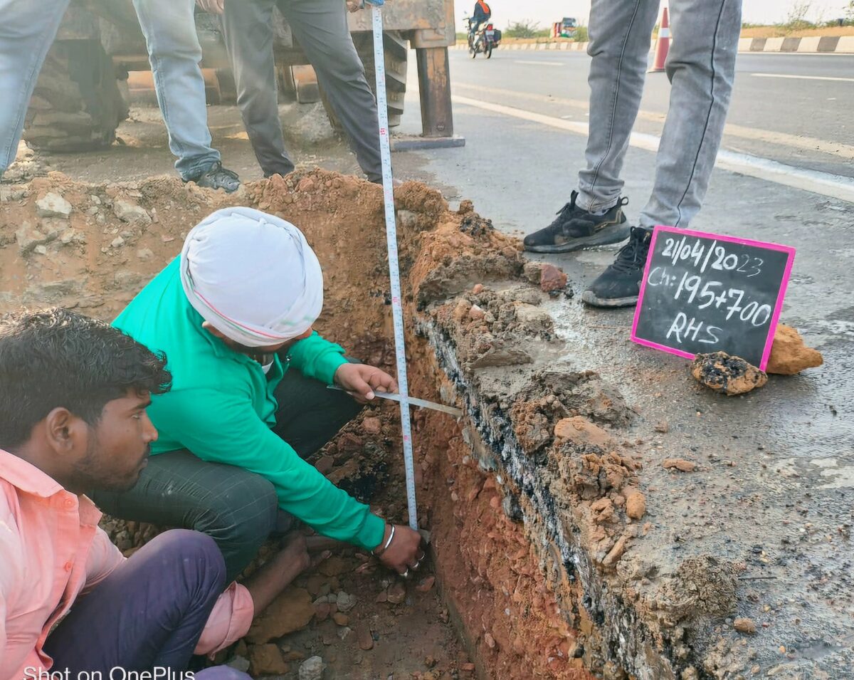
7.0 Setting Out
The limits of CTB layer shall be marked by fixing pegs on both sides at regular intervals. The chainage boards & Bench Marks shall be set outside the limits of construction.
8.0 Procedure
Construction operation shall be as per Clause 403.3 of MoRTH or Chapter 5 of IRC SP 89. Before laying CTSB/CTB on already prepared sub base/sub grade , the shoulder shall be constructed first in order to provide confinement.
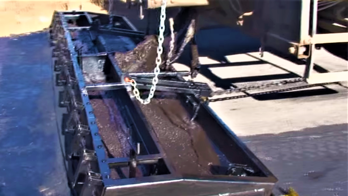
Material for the CTSB/CTB shall be prepared as per mix design in mixing plant. Moisture shall be maintained within tolerance range as determined by Mix Design. The mix shall be spread by a paver finisher in full width of a pavement as per approved drawing. In exceptional cases where it is not possible for the paver to be utilized, mechanical means like motor grader may be used with the prior approval of the Engineer. Maximum care shall be taken to spread the material uniformly. The compaction shall be carried out as per clause 403.3.5 with the help of vibratory roller of 8T to 10 T. Rolling shall be continued until the density achieved is at least 98 percent of maximum dry density.
The sub-base/base course shall be suitably cured for 7 days. Subsequent pavement course shall be laid soon after to prevent the surface from drying out and becoming friable. No traffic of any kind shall ply over the completed sub-base/base unless permitted by the Engineer.
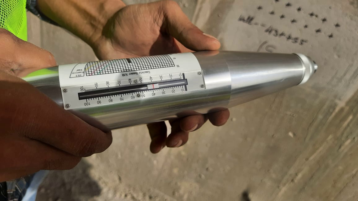
9.0 Quality Control and Testing
Quality control tests shall be done as per Quality Control Tests and Acceptance Criteria as set in MORT&H 5th revision. Of section 900.