METHOD STATEMENT OF REBUND HAMMER TEST

SCOPE: Compressive strength of concrete is very important criteria which can be easily computed by the Rebound Hammer .The rebound hammer is a nondestructive testing apparatus, whereby the rebound of the spring driven mass is measured after its impact with concrete surface. The output of the rebound hammer is referred to as rebound number and are correlated with surface hardness of concrete.

  1. RERFERENCE IS CODE: IS 516 (Part 5/Sec 4) : 2020
  2. PROCEDURE

a. For testing, smooth, clean and dry surface is to be selected. If loosely adhering scale is present, this should be rubbed off with a grinding wheel or stone. Rough surfaces resulting from incomplete compaction, loss of grout, spalled or tooled surfaces do not give reliable results and should be avoided.

b. The point of impact should be at least 25 mm away from any edge or shape discontinuity.

c. For taking a measurement, the rebound hammer should be held at right angles to the surface of the concrete member. The test can thus be conducted horizontally on vertical surfaces (preferably) or vertically upwards or downwards on horizontal surfaces. If the situation demands, the rebound hammer can be held at intermediate angles also, but in each case, the rebound number will be different for the same concrete.

d. Around each point of observation, six readings of rebound indices are taken and average of these readings after deleting highest and minimum reading means we have to take 8 readings

e. After the average reading find out the corresponding Compressive strength from the graph .

3. TEST RESULTS

Test result should record in in prescribed format

The report shall include the following:

a) Date/period of testing

b) Identification of the concrete structure/element

c) Identification of the rebound hammer;

d) Grade of Concrete

e) Test result and hammer orientation for each test area

Facebooktwitterredditpinterestlinkedinmail

HOW TO CONVERT 1:2:4 FROM VOLUME TO WEIGHT

A frequent question arriving in my email mailbox is “HOW TO CONVERT 1:2:4 FROM VOLUME TO WEIGHT ?” Most commonly, people are trying to find out how to convert from volume to weight  so in this article I am giving detail procedure for to convert from weight to volume.

For clarification I am taking table 9 from IS 456-2000

HOW TO CALCULATE

Calculation of materials required for 1 m³

Density of Cement = 1440 kg/cum

Volume of 01 bag (50 kg) of cement = 50 /1440 = 0.035 cubic meter (cum)

We know the ratio 1:2:4

Volume of Sand required would be = 0.035*2 = 0.07 cubic meter (cum)

Volume of Aggregate required would be = 0.035*4 = 0.14 cubic meter (cum)

Next step , you have to convert the volume and check for the feasibility from IS 456-2000  provision means water cement ratio maximum 32/50 =0.64 and all ingredient(coarse aggregate fine aggregate should not be more than 330 kg.

CONVERT VOLUME TO WEIGHT

For converting volume to weight you need dry loose bulk density , which can be determine by density box. Here we are assuming For sand 1450 kg/m³ and for aggregate take 1550 kg/m³.

Quantity of sand will be 0.07 x 1450 = 101.50 kg

And quantity of aggregate 0.14 x 1550 =217.0 kg

Cement =50 kg

And take W/C ratio 0.60 Water 0.60 X 50 = 30.0 kg but specified water is 32 kg hence O.K.

Specified All in aggregate should not be more than 330 kg(318.0 kg), hence O.K

So, One bag of cement (50 Kgs) has to be mixed with 101.50 kgs of Sand, 217.0 Kgs of aggregate and 30 kgs of water to produce M15 grade concrete.

MATERIAL REQUIRED FOR I M³

From the above calculation, we have already got the weights of individual ingredients in concrete . So, the weight of concrete produced with1 Bag of cement (50 Kgs)

=50 kg + 101.5 kg + 217 kg + 30.0 kg = 398.5 kg say 400 kg

Considering concrete density = 2400 kg/cum,

One bag of cement and other ingredients can produce = 400/2400

= 0.1667 m³ of concrete (1:2:4)

01 bag cement yield = 0.166 cum concrete with a proportion of 1:2:4

01 cum of concrete will require Cement required = 1/0.166 = 6.02 Bags Say 6 bags

Sand required = 101.5/0.166 = 611.44 Kg or 611 kg

Aggregate required = 217/0.166 = 1307.28 kg or 1307 kg

Water =30.0/0.166= 180.72 say 181 kg

INGREDIENT REQUIRED FOR 1:2:4 IN 1 M³ IN Kg

  • Cement 300.0 kg
  • Sand 611.0 Kg
  • Aggregate 1307.0 Kg
  • Water 181.0 kg
  • If ratio of 20 mm & 10 mm is 60% and 40%
  • Then 20 mm 1307 x 60%= 784 kg
  • 10 mm 1307 x 40%=523 kg
  • In the same manner you can calculate for M20
Facebooktwitterredditpinterestlinkedinmail

HOW TO CURE CONCRETE CUBE

As all over the world concrete is accessed by its compressive strength so curing of concrete cube in a proper manner having great importance .Concrete cube can be cured in a following manner:

  1. Leave the test specimens in the mould for at least 16 h, but not longer than three days, from the time of addition of water to the dry ingredients. Protect the specimens from shock, vibration and water evaporation. Store the specimens at a temperature of 27 ± 3 °C.
  2. After removal from the mould, submerge the test specimens in clean, fresh water immediately. Store the test specimens in water at a temperature of 27±2°C and take it out just prior to testing. Alternately, store the test specimens in a chamber at a temperature of 27 ± 2°C and a relative humidity of at least 95 percent until just before testing.
  3. If the test specimens are to be sent to a test laboratory, cover the test specimens with wet cloth or wet sand/ sawdust or other suitable material or seal the test specimens in plastic bags containing water to ensure that the test specimens are delivered to the test laboratory in damp condition not less than 24 h before the time of testing. At the test laboratory, store the test specimens in water at a temperature of 27 ± 2°C until taking it out just prior to testing.
Facebooktwitterredditpinterestlinkedinmail

PLASTIC SHRINKAGE CRACK

In simple way ,when fresh concrete has been placed in forms, concrete undergoes a volumetric contraction while it is in plastic state (before the concrete has set). This is known as Plastic Shrinkage,

Plastic Shrinkage are so-called because they form while the concrete is still plastic, ie has not set. Rapid drying of the surface of the plastic concrete causes it to shrink and crack.They rarely occur near the edges of a slab as at those locations the concrete is usually free to move.It can starts after 30 minutes of concrete pouring or during finishing.Plastic shrinkage cracking rarely impairs the strength of a concrete element.  

Main factors affecting plastic SHRINKAGE

  • The main reason behind plastic shrinkage cracking is considered to be rapid and excessive surface water evaporation of the concrete element in the plastic stage (freshly cast concrete) which in turn leads to the so-called plastic or capillary shrinkage1. Water/cement ratio: Low water cement ratio resulting high strength mixes resulting in early plastic shrinkage crack.2. Additives(Effect of superplasticizer on cracking): Higher doses of SP resulting in early crack.  3. Fines Content: More fines is liable to get plastic shrinkage crack.

    4. Depth of the concrete section: Deeper concrete section is less prone to plastic shrinkage cracking

    5. Curing measures- Poor or inadequate curing

    6. Effect of coarse aggregate content on cracking – Reducing the amount of the coarse aggregate in concrete mix leads to more plastic shrinkage and higher cracking risk.

    7. Type of cement – OPC 53 grade cement is very fine grinding and need more water to hydrate & liable to get crack.

    Practice To Minimize The Plastic Shrinkage Crack

  • To minimize the incidence of plastic shrinkage cracking: Dampen the subgrade and formwork , ensuring that any excess water is removed prior to placing concrete.
  • In hot weather, lower the temperature of the fresh concrete by using chilled mixing water  or any suitable method.
  • Do the concrete work , when temperature is below 35˚ C
  • Protect concrete surfaces from drying out by gunny bags or suitable means
  • Commence curing regime promptly after finishing and continue for the specified period.
  • Revibrate the concrete or use towel with pressing into the concrete and make finish before hardening the concrete.          
Facebooktwitterredditpinterestlinkedinmail

METHOD STATEMENT OF PILE CAP

A pile cap is a thick concrete foundation rest on concrete or timber piles that have been driven into soft or unstable ground to provide a stable foundation. It usually forms part of the foundation of a building or structure or it is the uppermost portion of a pile which acts to secure the piles in position and receive and distribute superstructure loads.

In this article we will discuss the method statement of pile cap in detail  with the help of following section:

  1. Equipment
  2. Procedure
  3. Safety

1.EQUIPMENT

  1. Excavator
  2. Dumpers
  3. Batching Plant
  4. Transit Mixers
  5. Truck / trailer
  6. Welding Generator
  7. Concrete Vibrators
  8. Concrete Needles
  9. Jack hammer
  10. Compressor
  11. Crane / Hydra
  12. De-watering Pump

* As per site condition above mentioned equipment can be increased or decreased.

2.Procedure

a.SURVEY:

Before commencing excavation, the pile cap area shall be marked on the ground after carrying out survey with reference to control points. After excavation the levels of the pit shall be checked for correctness to the drawings and recorded. Longitudinal and transverse centerlines shall be marked outside the pit for reference for cross checking the pile. The shift of pile shall be recorded by marking the theoretical co­ordinates of pile on ground and circle of equivalent to pile diameter shall be drawn and shift of actual pile will be measured from theoretical edges of pile. The as built details of the piles shall be recorded jointly. Based on shifted location of pile top, pile Cap / P.C.C. layout shall be marked to ensure minimum 150 mm offset from outer edge of pile. After laying of PCC, the layout of the pile cap shall be marked on it with reference to the reference points to facilitate tying of rebar and erection of shuttering.
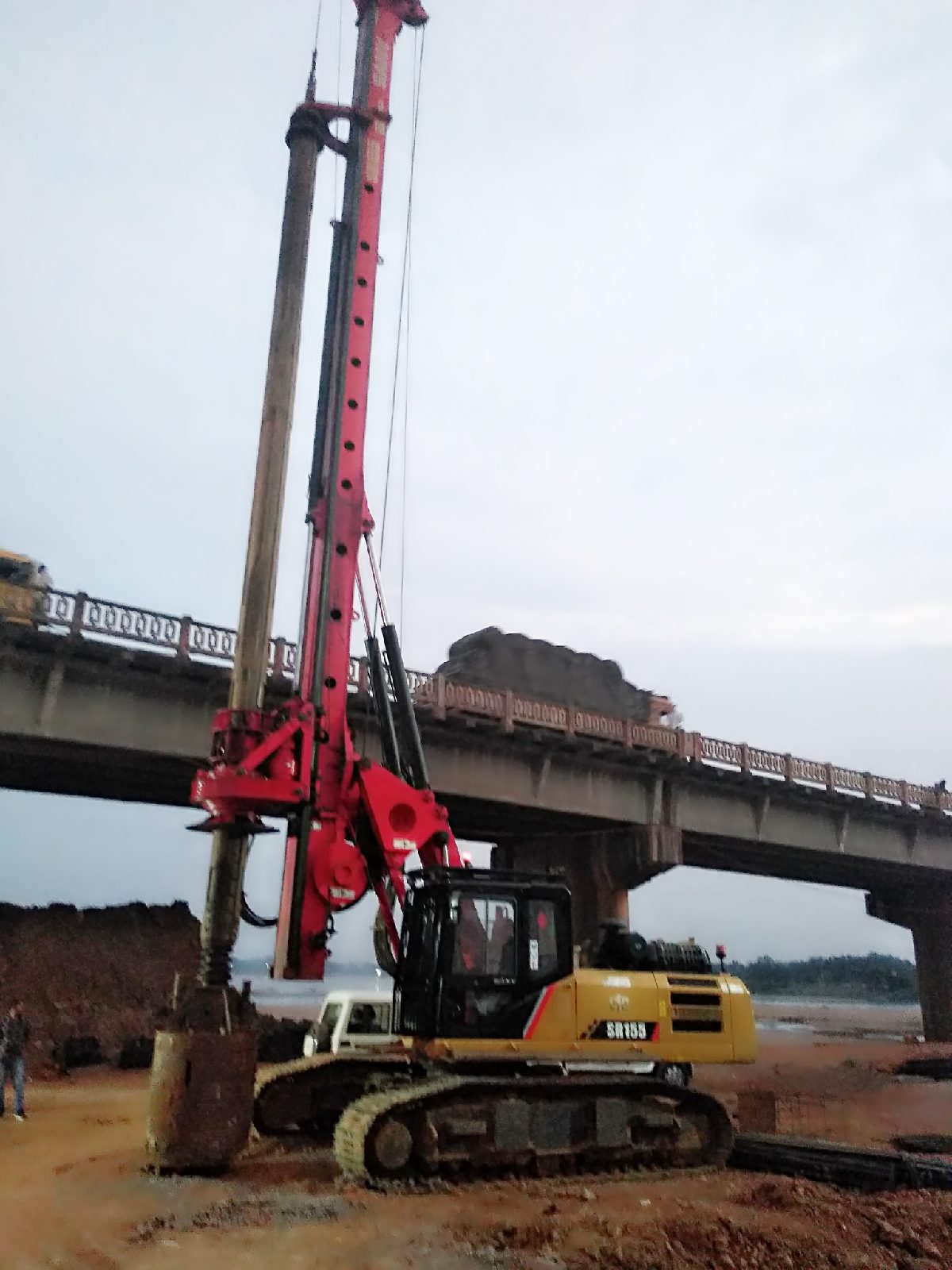
b.EXCAVATION:

Shoring shall be provided depending upon the stability of the soil found in the area. Shoring shall be done with the help of old steel plates and props. At road locations the pit shall be excavated to the dimensions providing working space all around the pile cap, to facilitate fixing of steel & erection of shuttering as detailed in the drawings. The last 300 mm excavation shall be carried out manually & leveling course shall be laid down within 36 hrs after completing excavation of last 200 mm depth. Provision for sump shall be made at the comer of the pit to pump out underground water of about 750 mm deep from PCC bottom. Also an earthen drain of about 200 mm width if required shall be provided all around pile cap dimension & it shall be connected with sump to drain off excess rain water/seepage water to ensure that the water table will at least 300 mm below the lowest level of the excavation before laying PCC. The excavated earth shall be then disposed by means of trucks / loaders.

c.REMOVAL OF LAITANCE:

After excavation the laitance of the piles shall be removed by using Pneumatic Jack Hammers seven days after casting of pile or manually three days after casting of pile. The top of pile after striping shall project 50 mm into the pile cap and reinforcements of pile shall be fully anchored in pile cap as per clause 709.5.2 of IRC: 78:2000. The debris of broken concrete shall be removed from the pit and disposed off to approve dumping sites. Exposed bars shall be straightened & cleaned properly with wire brush.
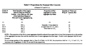
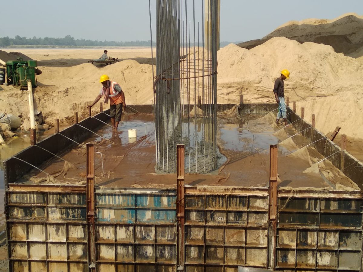
d. PCC:

After leveling the bottom of the bed, sprinkle some water to keep the soil moist. PCC of Mix M15 or specified in drawing shall be mixed at the centralized batching plant at the casting yard and transported to site in transit mixers. The concrete shall directly pour through chutes from three locations, shall be spread and leveled manually to the specified thickness shown in the drawing. PCC edges shall be projected 100 mm more than that of pile cap as detailed in the drawing to facilitate the fixing of form work and levels of PCC shall be jointly checked & verified. The PCC shall be cured by sprinkling water.

e.REINFORCEMENT

a) Fabrication: For fabrication of reinforcement, BBS shall be prepared as per the “Good for Construction” drawings. The Reinforcement shall be cut using cutting machines or manually as required and bent at Rebar yard. The re-bars shall either be transported to location in trailer / truck or cutting bending may be done at site depending upon the situation.

b) Fixing of Re-bars:

The re-bars shall be manually fixed into its position as shown in the good for construction drawing. Reinforcement of pile cap shall be lapped with the reinforcement of pile. Cover blocks of same grade of concrete in which these are to be embedded shall be provided at spacing of about 2.0 m c/c to ensure uniform cover as specified in the drawing and tied together with GI binding wire. After fixing the pile cap rebar, pier shaft rebar shall be erected. This rebar shall be supported by erecting a suitable staging frame across the width of the pile cap. The rebar cage shall be checked as per checklist given in QA manual and RFI for inspection shall be raised with IE. The rebar, chairs, spacers & laps shall be jointly checked after completion of cage placing. Sufficient chairs and spacers shall be provided to keep the cage in its proper position. After getting the clearance, balance shuttering work will be taken up. Pier dowels shall be hold in position rigidly to prevent it from buckling.

f.SHUTTERING

Shuttering fabricated as per approved drawings shall be placed at locations as per the pile cap dimensions shown in the good for construction drawing. Reinforcement shall be fixed as per the drawing and marking the layout on PCC for pile cap. After completing the fixing of rebar cage shuttering shall be erected & fixed on the layout drawn on PCC. Before fixing, the shuttering area shall be cleaned with wire brush & approved shuttering oil shall be applied on concrete face. After fixing of shuttering it shall be checked as per QA checklist and RFI to be raised for inspection of IE. For preventing leakages from joints, rubber strip/foam strip shall be provided at the joints of shuttering plates. Proper side supports/bracings/tie bars shall be provided to resist lateral pressure of green concrete during pouring.
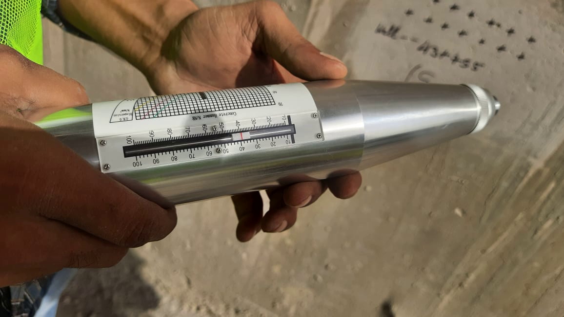
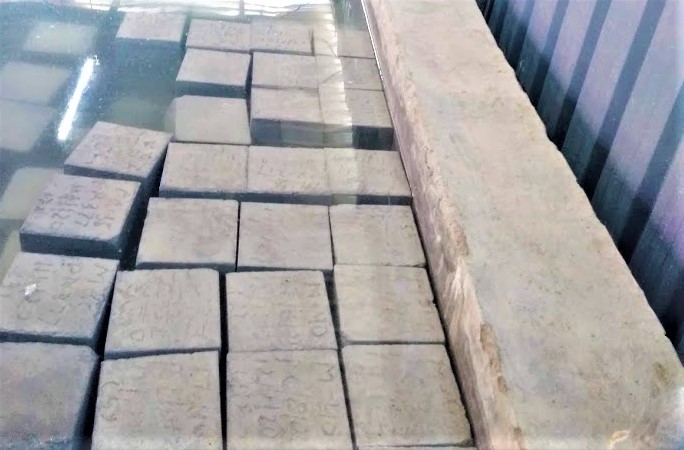
g.CONCRETING

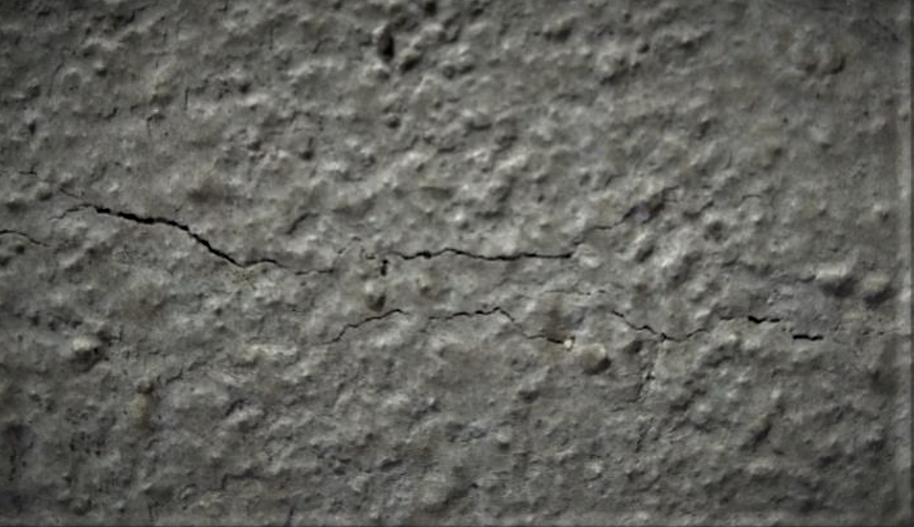
The required (M-35) grade concrete shall be produced as per the approved concrete design mix from the centralized batching plant and transported by transit mixers to the pouring location. Before pouring concrete, slump of 80 mm to 130 mm shall be checked at pouring location. The concrete shall be placed by concrete pump /placer boom or by direct chutes. Concrete placing commences from one end to another in cascading manner till completion. The drop height of the concrete should not be more than 1.5 m. The concrete shall be vibrated using 60 mm / 40 mm diameter needle vibrators. Concrete cubes shall be taken for testing of compressive strength as per IRC 21 at pouring location. Concreting should be done in such a way that next layer of concrete should be laid before initial set of concrete of previous layer to avoid cold joints. Regular tamping shall be done during & after concreting operation.

h.CURING

 Date of concrete shall be written on the concrete surface to ensure curing up to the specified   duration after date of casting.

The concrete shall be cured by ponding method. Bunds of cement mortar of lean mix shall be built after the concrete attains final setting time after casting of concrete, these bunds shall be filled with water from approved source. The sides of the pile cap shall be covered with Hessian cloth till back filling is started. Further curing is ensured by keeping the backfill moist with water.

i. BACKFILLING

Immediately after de-shuttering, concrete surface shall be checked jointly and get the approval for backfilling. Back filling with local earth available or excavated material shall be carried out in layers of 250 mm (compacted thickness).(as per MORT&H clause no – 304.3.7)

The compaction shall be done with the help of suitable equipment such as rammer or plate vibrator etc., after necessary watering, so as to achieve a density not less than required  field density .

j.MISCELLANEOUS WORKS

After backfilling the damaged roads, if any shall be repaired immediately preferably within 15 days of backfilling as per specification before removing of the barricades, the whole area shall be cleaned after completion of work.

  1. SAFETY:- All safety precautions shall be taken as per safety manual submitted by us. Further the preparatory works shall also be carried out as per Diversion plans separately submitted for construction activities on urban areas.

1.A width of approx.8.00 m (outside to outside of barricading) shall be barricaded along road for purposes of construction of pile caps. This can be increased at specific location with prior approval of Engineer.

2.Suitable reflectors, blinkers, diversion board, painting of barricade etc. shall be done to caution the road users and for their safety. Working space shall be well illuminated during work at night.

3.All site personnel shall wear helmets, safety shoes and other safety devices as required.

4. Proper precautions and safety arrangements shall be used for activities like welding, handling of reinforcement, fixing of formwork, electrically operated equipment etc.

Facebooktwitterredditpinterestlinkedinmail

PILING METHOD STATEMENT

When the soil intended for the foundation is not capable of supporting a structure , deep foundations are required to transfer the loads to deeper strata. A pile is a slender structural member made of steel , concrete or wood.These days piles are more in trend rather than in well foundation .In this article we will discuss the typical method statement pertaining to pile.We had divided the method statement into 7 sections for easiness

1.Scope of Work

  1. Equipment
  1. Material
  1. Method Statement
  1. Tolerances
  1. Routine Test
  1. Integrity Test
  1. Scope Of Work This work consist of Pilling work -1200 mm dia. Bored piles Boring and Installation of 1200 mm dia .
  1. Machineries/Equipment  The following machineries shall be deployed at each working site.
  • Rotary rig -3
  • Augur of 1200  Size -3 Nos.
  • Drilling bucket of suitable size -3
  • Cleaning bucket (skip bases) -3
  • Crane 20 ton capacity -3
  • Slurry sampler -3
  • Metallic chain 25 m-3
  • Steel tape 30 m & spirit level plumb- 1 set at every site of
  • Jar& bucket and hydrometer – 1 set at every site of
  • Steel plate circular liner 6 mm thick and 5 m long -2  at every site or as required.
  • Steel rectangular tank of 20,000 litre capacity each -3 at each site,
  • Bentonite agitator with 3 HP motor -1 No at each
  • Flushing pumps 5 HP capacities -2  at each site.
  • Diesel pump 10 HP standby -1 No
  • Water tanker -1 No
  • JCB-1 No
  • Dumper/Tipper-2
  • Generator 62 KVA -1
  • Welding Transformer -2
  • Tremie pipes 200 mm  of different lengths as required for proper concreting.
  • Hopper 4 M³ capacity with plug at each site.
  1. Material

3.1 Bentonite – The betonite (drilling mud) shall be arranged of approved quality and shall be stored about 30 cms in water tanks  , 5% of bentonite by weight of water may be used subject to ensuring appropriate density

  • Density of suspension               =1.05 gm/cc
  • Silt content                                    = <1%
  • PH value                                          = 5 -12
  • Liquid Limit (not less than )  = 400

3.2 Concrete

  1. Grade of concrete                                 = M 35
  2. Slump                                                        = 150 -200
  3. Temperature                                           = < 40°c
  4. Minimum cement content               = 400 kg./ M³
  5. Maximum size of Aggregate           = 20 mm

3.3 Reinforcement

  • T.M.T bars FE 415/500 shall be used. Reinforcement cage shall be fabricated after cleaning as per approved bar bending schedule.
  • Stiffeners as show in the drawings. and cover blocks prepared out of non – shrink mortar of approved quality shall be provided and reinforcement shall be tied with 18 SWG binding wire and welding may be done only where necessary after providing suitable lap length. The clear cover of 75 mm shall be kept.
  1. Method Statement

4.1 Layout

  • The layout of piles shall be carried out with the help of Total Station only.
  • Grid /axis lines shall be established by total station as shown in the approved drawings and four Nos. reference points for each pile shall be established, in such a way so that these do not get disturbed during  piling work.
  • The ground levels shall be recorded with the help of auto level and the length of the piles shall be evaluated.
  • The nomenclature of pile group shall be designated clock wise or Anti              clock wise with specified location mentioning grid /axis.

4.2 Procedure

  • The pre-trenching shall be carried out to detect the utility (if any). Manual trenching in transverse and longitudinal direction shall be done near pile location up to about 2 m in depth or as required.
  • A circular pit shall be dug out for outer dia for steel casing manually for a depth of 1 m. The centre of pit shall be checked accurately from reference points.
  • Drilling by auger up to depth of casing shall be done.The steel casing shall be fixed with the help of rotary rig collar guide, truly in centre of hole as well as vertical.
  • The verticality of Kelli bar shall be checked by spirit level in two directions at bucket top level.
  • The casing shall be checked by plump bob also.
  • The verticality & levels are seen in cabin of Rotary Rig at Instrument display board.
  • Beyond casing depth of 5 m the drilling bucket shall be used.
  • The bentonite shall be mixed in tank mature for at least 8 hrs. before actual use and during feedings it shall be agitated.
  • The density of bentonite shall be checked during boring.
  • Verticality and depth shall be recorded as per Rotary Rig panel board.If it is not so, suitable measures shall be taken to rectify tendency of the bore to go beyond the centre point.
  • The cleaning bucket / skip box shall be used for the last 30 cms depth to achieve required founding level and for cleaning of mud.
  • The sounding shall be taken by using metallic chain.
  • The soil strata shall be recorded at every 3 m or at the change of strata.
  • Soil samples shall be kept for record in polythene bags marking the depth and pile no.
  • If there are chances of bore collapse, extra liner shall be provided upto a suitable depth.

4.3 Acceptance limits

  • Verticality – It shall not exceed 1 in 50.
  • Shift – The resultant shift in any direction from the location designed at cut off level shall not exceed 50 mm and shall be measured at pile cut off level.

4.4 Movement of Rig and Machines

The sequence of concreting of pile would be such that reference pillars are not damaged during movement or rig /machines.

4.5 Clearing of Bore Hole and flushing

  • The reinforcement cage duly welded at joints shall be lowered by crane. The cage shall be kept at the requisite level by suspending from collar.
  • Cleaning of the bore hole shall be done by the circulation of bentonite slurry of 1.05 gm/cc under high pressure through tremie pipe, which shall be kept max 150 mm above the bottom of bore.
  • During flushing the bentonite slurry shall be agitated and sufficient quantity of Bentonite Slurry shall be available.
  • This process shall be continued till the slurry at the bottom is of density 1.10 gm/cc .However care shall be taken to avoid bore collapse due to excessive flushing.
  • The slurry sampler shall be used to take the sample from bottom of the bore.
  • Concreting shall not be done, if density of bentonite slurry from bottom is more than 1.10 gm/cc.
  • The bentonite slurry carried out from bore, shall be pumped to next container so that the mud settles down.
  • The dugout earth and muck shall be removed immediately, and disposed off at approved disposal areas.
  • There shall be no over flow of slurry on road of working space.

4.6 Concreting

  • Concreting under water shall be placed in on continuous operation by tremie pipe So that concrete entering the tremie pipe shall not get mixed with the slurry.
  • The tremie pipe of minimum 200 mm dia with water tight joints using rubber seal shall be kept 200 mm above bottom of hole with attached hopper of 0.4 M³ capacity duly held by crane of 20 T capacities.
  • The approaches for movement of transit mixers shall be kept clean with suitable ramp near bore for easy pouring of concrete.
  • The 3 nos. of transit mixers shall be sufficient to maintain continuity of concrete, so that there shall be no interruption. The rate of pouring concrete shall be approximately 6M³ /hour.
  • First charge of concreting shall be done by using a stopper at the bottom of funnel. Stop shall be kept in such a way that it can be removed with least resistance.
  • The tremie pipe bottom shall be done by using a stopper at the bottom of funnel.
  • Pieces of tremie pipe shall be removed as per calculated depth of concrete. It shall be ensured that the end of the tremie pipe should always be in concrete to avoid slurry and muck mix with concrete.
  • If the delay during concreting is more than 2 hrs Cement slurry shall be used for mobilizing concrete inide the tremie pipe.If concrete pouring is delayed due to any reason.
  • The bentonite slurry shall be re-circulated to avoid settlement of suspended particles of earth. The sounding shall be taken after each load of concrete.
  • The slump test and concrete cubes shall be casted from each transit mixer as specified for concrete work.
  • The actual quantity of concrete if less than 10% of theoretical consumption shall be immediately reported to EIC.
  • The length of concrete above cut off level shall be at least 1.00 m.

4.7 Removal of guide casing

  • Casing shall be extracted by smooth pull and push movement.
  • Precaution shall be taken that concrete and reinforcement are not disturbed.

4.8 Breaking of pile head

  • The breaking of extra concrete shall be done after a minimum of 7 days of concreting.
  • The breaking can be done by pneumatic jack hammer or manually as per Direction of Engineer in charge.
  • The pile shall be cut off as indicated on drawing
  • The exposed reinforcement shall not be damaged while breaking the pile head concrete.
  • All dismantled material shall be disposed off at approved disposal areas.
  • The height for 150 mm above cut off level shall be chipped off manually to avoid damage to pile.
  1. Tolerances
  • Variation in diameter + 50 mm -10 mm
  • Variation from vertical -1 in 50
  • Variation in final position of head in plan =50 mm
  • Variation in level of top of pile +25 mm
  1. Routine Test
  • General arrangements for routine vertical test shall be made according to IS 2911 (P-IV).
  • Routine load test shall be carried out for 1.5 times of working load to determine the Safe load on pile.Safe load on pile shall be 2/3 of the load at which settlement is 12 mm.
  • The pile to be tested shall be selected by Engineer in Charge from any working pile groups.
  • The pile shall be tested after concrete achieves designed concrete strength.
  • Datum bar made out of MS Channels of size 125 mm shall be fixed on both side of the main girder such that the clear distance between the supports is at least a distance of 3D (D being dia of pile ) from the edge of the pile. Care shall be taken to ensure that the Datum bars do not get disturbed during loading.
  • Breaking of false concrete shall be done upto a level 50 mm above cut off level. The pile head shall be build up using non – shrink mortar.
  • The sub grade shall be built upto required level by properly compacting. approved kentledge arrangement shall then be placed in position,
  • Placing of base slab and concrete blocks upto required width and level shall be carried out.
  • Bottom and top plate shall be placed over jack and stool packing packing plate if required shall be used to fill the gap between main girder and jack
  • Placing main girder over concrete blocks after maintaining required gaps for settlement of secondary girders.
  • Level and weld the kentledge wherever necessary concrete fill shall be done in gap of concrete block and base girders.
  • Loading of blocks shall be done in layers as per drawing upto required test load plus 25% extra.
  • Concrete block in alternate layers shall be secured with 16 mm Ф wire rope and turn buckle after erecting scaffoldings.
  • Adequate precaution shall be taken for safety of adjacent traffic viz placing caution boards, barricades, blinkers, flags etc.
  • Four nos. dial gauges (deflect meters) shall be fixed from datum bar at four corners of the pile head. The least count of these shall be 0.001 mm
  •  All the pressure gauges, dial gauges shall be tested and calibrated before use.
  • Increment of load shall be @ 20% of design load .
  • Increment of test load and displacement in each stage of load shall be maintained till rate of displacement of pile top is either 0.1 mm in first 30 min. or 0.2 mm in the first Hour or till 2 hrs which ever occur first.
  • The final load of 1.5 times the design load shall be maintained for 24 hrs.
  • The load shall be released and rebound shall be recorded.

Integrity Test

  • Pile integrity test shall be carried with electronic analyzer.
  •  The test shall be carried out by approved agencies.
  • The test shall be carried out on 10% of working piles.
  • Records shall be submitted with recommendation.

Facebooktwitterredditpinterestlinkedinmail