Blog

QUALITY CONTROL ENGINEER INTERVIEW QUESTION & ANSWER

In this competitive market , facing interview is very difficult , if you’re trying to find employment that is expounded to Quality Control Engineer in highway project & you wish to organize for the 2020 highway project Quality Control Interview queries. it’s true that each interview is completely different as per the various job profiles. Here, we’ve got ready the necessary Quality Control Interview question and answers which is able to assist you get success in your interview.

In this article, we have a tendency to shall gift fifty two  most vital and often asked Interview question in big and reputed organization like L&T , Afcons & Tata consultancy etc. These interview can be in the following trend:

  • Q 1 . Tell me about yourself in brief ?
  • Ans: “Hello, my name is XYZ. I am a professional with a degree/diploma in Civil Engg in 20xx . My qualifications include xyz years of experience in infrastructure project especially in Highway Project & deals with quality control aspect.
  • I started my carrier with building project with XXX(Name of First company) as a Diploma / Degree Trainee Engineer and after that gone to YYY (Name of second company) as Quality Control Engineer ; after 2017 , I engaged in highway project and joined in ZZZ (Name of third company) & successfully completed one/two National /State highway project.
  • At present, I am responsible for Soil/Concrete/ GSB/Bituminous work & assisting my boss to doing concrete /GSB /CTB /Bituminous mix design.

Q 2. What is the name of your Material Engineer?

Ans : The name of my material Engineer is Mr xyz

Q 3. What is the minimum CBR of subgrade soil ?

Ans : As per IRC 58-2015 Clause 5.7.3.6 , a minimum CBR of 8 % is recommended for 500 mm of selected soil used as subgrade.

Q 4.What is code reference from which you are performing CBR test with 3 energy level as per MORTH 5 revision ?

Ans : AASHTO Designation: T 193-99 -2003

Q 5. What is the limit of Air Voids , flow & VFB in Dense Bituminous Macadam mix design ?

Ans : The limit of Air voids , flow & VFB is 3 -5% , 2- 4 mm & 65-75% simultaneously.

Q 6.How much staff is working under you , draw the organization chart & show your position ?

Ans : Total xyz staff is working under me is xyz , draw a diagram on your own & make practice.

Q 7.What should be the minimum required density of Subgrade soil as per MORT&H 5th revision ?

Ans : 17.5 KN/m³ or 1.78 gm /cc

Q 8 What is the softening point of VG 30 & VG40 grade bitumen ?

Ans : The softening point of VG30/VG 40 grade bitumen is 47 ºC / 50ºC

Q 9. What will be the maximum allowable size of granular material for subgrade soil as per MORT&H specification ?

Ans : Allowable size of granular material in subgrade is 50 mm

Q 10. What is the maximum Liquid Limit & Plasticity Index allowed in earth work in embankment/subgrade soil ?

Ans :Clay should have Liquid Limit less than 50 % & PI should always be less than 25 %.

Q 11. What is the frequency of taking core for BM/DBM/BC for checking of compaction & thickness of laid layer as per MORT&H 5th revision ?

Ans : One core at 700 m²

Q 12.What is the maximum Aggregate Impact Value of aggregate allowed for Bituminous concrete(BC) work in flexible pavement ?

Ans : AIV should not be more than 24%.

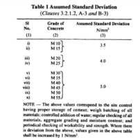
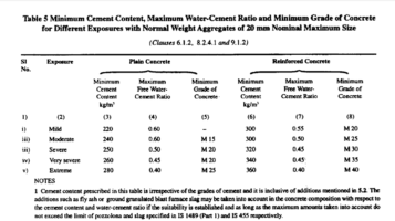
Q 13. What is the minimum cement content & maximum W/C ratio for M 25 RCC concrete for moderate condition as per MORT&H 5TH Revision ?

Ans : Minimum Cement Content 340 Kg & Maximum W/C ratio is 0.45

Q 14. What is the density frequency of compacted layer in Embankment & subgrade/Shoulder ?

Ans : 1 set of 10 test for 3000 m² of Embankment / 1 set of10 test for 2000 m² of Subgrade/Shoulder.

Q 15. What is difference between Specific Gravity & Density ?

Ans :Bulk density is the ratio between soil weight to the total volume of the soil  but Specific Gravity (G) is the ratio of the weight in air of a given volume of soil solids at a stated temperature to the weight in air of an equal volume of distilled water at that temperature . Specific gravity has no unit and it is generally used in design of concrete/bituminous mix.

Q 16. What is the maximum Aggregate Impact Value of aggregate for concrete work ?

Ans : 45%

Q 17 .What is the rate of spray of Prime Coat over WMM ?

Ans : 0.7 -1.0 kg/m²

Q 18.Which IS code specified the specification of aggregates ?

Ans : IS 383-2016

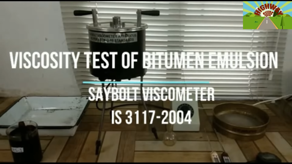
Q 19. How much Kinetic Viscosity of VG 40 bitumen is ?

Ans : The Kinematic Viscosity of VG 40 grade bitumen is 400 cst minimum at 135 º C.

Q 20. What is the dry density of WMM & GSB material in your project ?

Ans : The density of WMM/GSB in our project is 2.23 /2.24 gm/cc

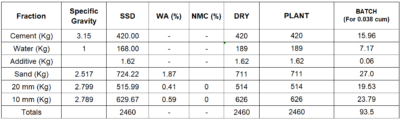
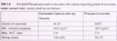
Q 21.What is the minimum cement content & maximum W/C ratio for Pile concrete as per IRC 78 -2014 Cl 709.1.9 ?

Ans : Minimum amount of cement  content 400 kg/m³ & maximum W/C ratio is 0.40

Q 22.What will be the minimum cement content as per IRC SP 49 2014 for DLC mix design ?

Ans : 140 kg / m³

Q 23 .How many samples you take for 900 m² of DLC laying ?

Ans : 3 samples (9 Cubes)

Q2 4. What is the Nominal size of aggregate for grade 1 Bituminous Concrete?

Ans : 19 mm

Q 25.What is the maximum limit of FI+EI for Dense Bituminous Macadam as per MORT& H 5th revision ?

Ans: Maximum FI+EI limit is 35%

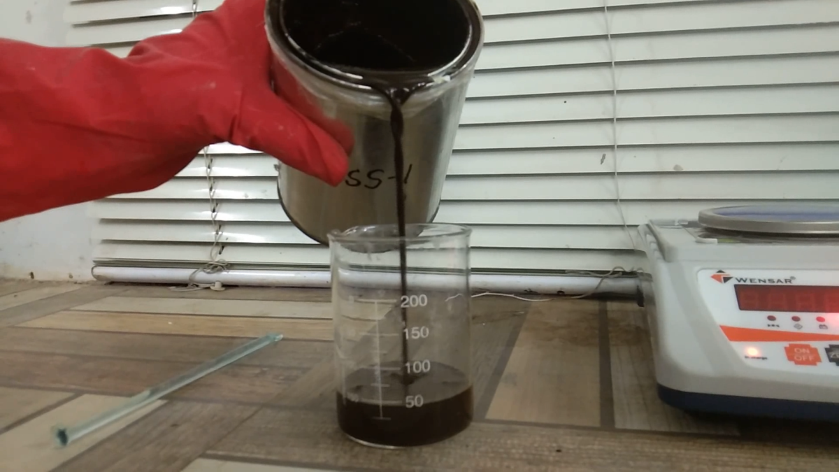
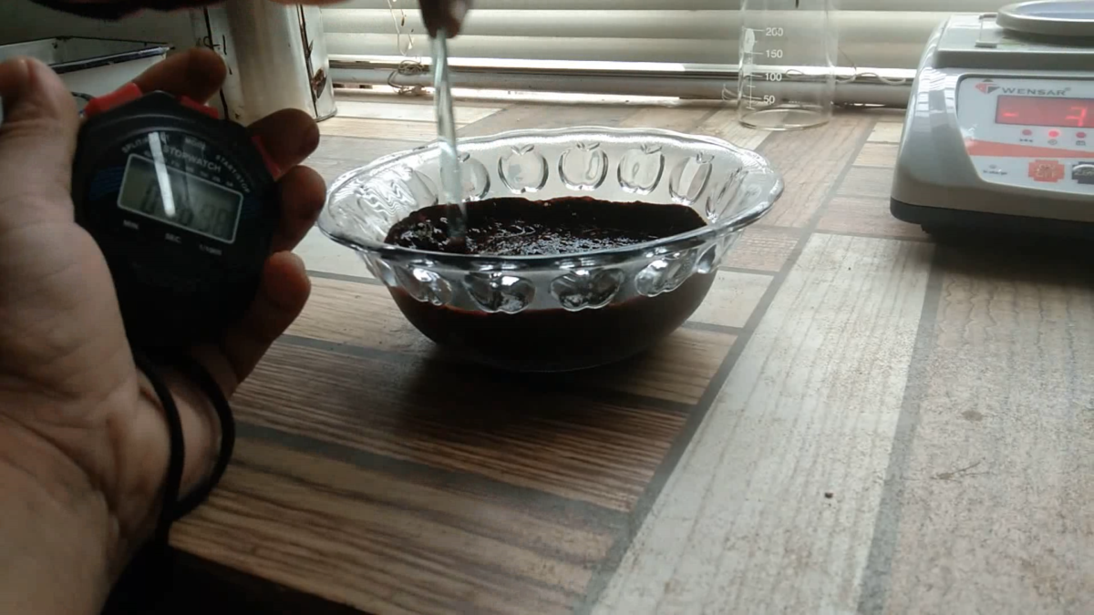
Q 26.What is setting time RS1 & SS1 Emulsion?

Ans: 15 to 30 minutes for RS1  & 24 hours for SS1  

Q 27. How many cube mould required for 110 m³ concrete ?

Ans: 4 +1+1=6 samples means 18 cubes as IS 456-2000

Q 28. As per MORT&H 5th revision how many grades of GSB are there?

Ans : Six grades are there.

Q 29. From which IS code  concrete mix design is being done ?

Ans: IS 10262 -2009 now the latest revision introduced IS 10262-2019

Q 30. On what temperature  Kinetic Viscosity test of any bitumen is being done ?

Ans = At 135 º C

Q 31. What is minimum bitumen content as per MORT&H 5th revision in DBM & BC for grade 1 mix ?

Ans : DBM 4.0 % & BC 5.2 % Minimum for the aggregate having specific gravity below 2.7.

Q 32. What is Compaction parameter of Bituminous Concrete ?

Ans : Relative density minimum 92% of Gmm of that day

Q 33. How much water can reduce the Superplasticizer ?

Ans : Practically more than 30 %

Q 34 What is the relation between Air Voids & Density ?

Ans : Air voids is inversely proportional to Density i.e If Air Voids are increasing density will be decreasing & reverse versa

Q 35.In tack coat which type of emulsion is used?

Ans : RS1

Q 36. What is the minimum rolling & laying temperature for VG grade 30 DBM/BC mix ?

Ans : Minimum laying temperature for laying is 140 º C & minimum rolling temperature is 90 º C.

Q 37.In prime coat what type emulsion is used as per MORT&H 5th revision in Indian condition ?

Ans : SS1

Q 38. What is the minimum sand equivalent value of crusher dust if to be used in Bituminous work ?

Ans : 50 %

Q 39.What does mean by VG 40 Bitumen ?

Ans : . Kinematic viscosity at 135º C, is 400 cSt, min.

Q 36. What is the minimum rolling & laying temperature for VG grade 30 DBM/BC mix ?

Ans : Minimum laying temperature for laying is 140 º C & minimum rolling temperature is 90ºC.

Q 37.In prime coat what type emulsion is used as per MORT&H 5th revision in India ?

Ans : SS1

Q 38. What is the minimum sand equivalent value of crusher dust if to be used in Bituminous work ?

Ans : 50 %

Q 39.What does mean by VG 40 Bitumen ?

Ans :  Kinematic viscosity at 135 º C, is 400 cSt, min

Q 45.Can you tell the name of IRC SP guide line for Quality System for road construction highway & Road bridge  ?

Ans: IRC SP 57 – 2000 but now latest revision with change the name also is IRC SP 112 -2017 & IRC SP 47-1998 for Road Bridge

Q 46. Which apparatus is used for softening point ?

Ans : Ring & ball apparatus

Q 47. What is the Rate of spread of Prime coat/Tack Coat ?

Ans: Three test per day

Q 48.Why you want to leave your present company?

1.I’d really love to be part of your project from beginning to end, and I know I’d have that opportunity here.

2. In my current role, I’ve learned many new skills. I’m looking for a position in which I can continue to grow that skill set in new circumstances.”.

3. I’ve learned a lot in my current role, but I’m looking for an opportunity that provides more challenges as I continue developing my skills and abilities.”

Q 49.Tell me your 5 strong point?

Ans: 1.Flexibility to handle any situation

2. Good Communication

3.Work under pressure

4.Dedication

5.Honesty

Q 50.Tell me your achievement in your carrier?

1.Re-organized something to make it work better

2.Identified a problem and solved it

3.Developed or implemented new procedures or systems

4.5.Worked on special projects

Received awards/Certificate

Q 51.What is your salary expectation?

Ans: This is your most important negotiation. Never lie about what you currently make, but feel free to include the estimated cost of all your fringes, which could well tack on 25 -30% more to your present “cash-only” salary.

Q 52.How much time you required to join ?

Ans: Always says one month but handle this situation very calmly. if you are ideal & have no job , can say within 7 days.


Facebooktwitterredditpinterestlinkedinmail

Concrete Mix Design Of M35 Grade(Pile) as per IS 10262:2009

1.STIPULATIONS FOR PROPORTIONING

a) Grade designation : M35 RCC (Pile)

b) Type of cement :53 grade Ordinary Portland Cement conforming IS 12269

c) Maximum nominal size of coarse aggregate : 20 mm

d) Minimum amount of cement  : 400 kg/m³ as IS 2911-Part 1/Sec 2 & IRC 78-2014.

e) Maximum water-cement ratio : 0.40 as per IRC 78 -2014 ,Cl  709.1.9

f) Workability : 150-200 mm slump as per IRC 78-2014 , Cl  709.1.9

g) Exposure condition : Moderate (For Reinforced Concrete)

h) Method of concrete placing : Trieme

j) Degree of supervision : Good

k) Type of aggregate : Crushed Angular Aggregates

l) Chemical admixture type : Super Plasticizer Normet

2.TEST DATA FOR MATERIALS

a) Cement used : Sagar 53 grade Ordinary Portland cement conforming IS 12269

b) Specific gravity of cement : 3.14

c) Chemical admixture : Super Plasticizer conforming to IS 9103 

d) Specific gravity of

1) Coarse aggregate 20 mm : 2.799

2) Coarse aggregate 10 mm: 2.789

Combined Specific Gravity of aggregate ( 20 mm-45% & 10 mm 55% )=2.792

2) Fine aggregate : 2.517

e) Water absorption:

1) Coarse aggregate 20 mm : 0.41 %

2) Coarse aggregate 10 mm  : 0.59

3) Fine aggregate           : 1.87 %

f) Aggregate Impact Value : 20.52

g) Combined Flakiness & Elongation Index : 27.57 %

h) Sieve analysis:

1) Coarse aggregate: Conforming to all in aggregates of Table 2 of IS 383

2) Fine aggregate : Conforming to Grading Zone III of Table 4 of IS 383

3 TARGET STRENGTH FOR MIX PROPORTIONING

f’ck =fck + 1.65 s    where

f’ck = average target compressive strength of concrete at 28 days,

fck = characteristics compressive strength of concrete at 28 days,

S = standard deviation.From table 1 of  IS 456 & IS 10262  assumed Standard Deviation, s = 5 N/mm² ; therefore target strength of concrete = 35 + 1.65 x 5 = 43.25 N/mm². Can adopt  this value while doing the concrete mix design those who are working other than highway project.

But as per MORT&H Table 1700.5 required target mean compressive strength = 35 + 12 = 47.00 N/mm²  where 12 is the current margin. Adopt this value those who are working in highway project.

4 SELECTION OF WATER•CEMENT RATIO

Based on the trial , adopted water cement ration 0.40

From the Table 5 of IS 456 maximum Water Cement Ratio for moderate condition is 0.50

As per Section 709.1.9 of IRC 78, maximum water cement ratio is 0.40 

so 0.40 is satisfying  all codal provision  whether it is  IS 456 or MORT&H

0.40 < 0.50 = 0.40 hence ok.

 5 SELECTION OF WATER CONTENT

From Table 2 of IS 10262:2009, maximum water content for 20 mm aggregate = 186 litre (for 25 to 50 mm slump range)

but for an increase by about 3 percent for every additional 25 mm slump so here estimated water content for 175 mm slump

= 186+(15/100) x 186

= 213.9 or 214 liter.

Based on trials with Super plasticizer water content reduction of 21.50% has been achieved.How it comes , see below calculation:

Water requirement , if  we intended to keep cement 420 kg for &  w/c ratio 0.40 for our concrete mix design  calculated water will be 168.0 liter ,  so required reduction in water when using superplaticizer  = 100 – (168/214 x 100) = 21.50 %.

Net required water = 214 – (214 x 21.50) % = 214 –46.1 = 167.99 liter say 168 liter.

Note :For 75 mm slump increase 3% , for 100 mm increase 6% , increase 9 % for 125 mm slump, increase 12 % for 150 mm slump & increase 15 % for 175 mm slump

6 CALCULATION OF CEMENT CONTENT

As discuss earlier adopted  based on trial w/c Ratio = 0.40

Cement Content = 168.0/0.40 = 420 kg/m³

As per IS 2911-Part 1/Sec 2 minimum cement content for tremie concrete is 400 kg/m³.

(As per Section 709.1.9 of IRC 78 – 2014 minimum cement content  400 kg & maximum water cement ratio is 0.40 specified)

but we had taken 420 kg/m³ > 400 kg/m³ hence ok.

7 PROPORTION OF VOLUME OF COARSE AGGREGATE AND FINE AGGREGATE CONTENT

As per table number 3 of IS 10262:2009 volume of coarse aggregate for 20 mm nominal size aggregate and fine aggregate (Zone III) for having water-cement ratio of 0.50 =0.64 (a)

In the present case water-cement ratio is 0.40. Therefore. volume of coarse aggregate is required to be increased to decrease the fine aggregate content. As the water-cement ratio is lower by 0.10. the proportion of volume of coarse aggregate is increased by 0.02 (at the rate of -/+ 0.01 for every ± 0.05 change in water-cement ratio). As the water-cement ratio is lower by 0.10. The proportion of volume of coarse aggregate is increased by

= (0.10/0.05) = 2.0 times of 0.01 so  0.01 x 2.0= 0.020 (b)

=  a+b = 0.64 + 0.020 =0.66

(at the rate of -/+ 0.01 for every ± 0.05 change in water-cement ratio).

Therefore, corrected proportion of volume of coarse aggregate for the water-cement ratio of 0.40 = 0.66

NOTE – In case the coarse aggregate is not angular one, then also volume of coarse

aggregate may be required to be increased suitably based on experience & Site conditions.

For pumpable concrete these values should be reduced up to 10%. Therefore, volume of coarse aggregate =0.66 x 0.9 =0.59.

Volume of fine aggregate content = 1 – 0.59 = 0.41.

8 MIX CALCULATIONS

The mix calculations per unit volume of concrete shall be as follows:

a) Volume of concrete = 1 m³

b) Volume of cement = [Mass of cement] / {[Specific Gravity of Cement] x 1000}

= 420/{3.15 x 1000} = 0.133 m³

c) Volume of water = [Mass of water] / {[Specific Gravity of water] x 1000}

= 168.0/{1 x 1000} = 0.168 m³

d) Base on trial we had kept admixture 1.0 percentage by weight of cement

 Volume of admixture  = [Mass of admixture ] / {[Specific Gravity of admixture ] x 1000}

= 4.2 /{1.090 x 1000}

= 0.0039 m³

e) Volume of all in aggregate = [a-(b+c+d)]

= [1-(0.133+0.168+0.0039)]

= 0.695 m³

f) Mass of coarse aggregate= e x Volume of Coarse Aggregate x Specific Gravity of  coarse Aggregate x 1000

= 0.695 x 0.59 x 2.792 x 1000

= 1144.86 kg/m³

g) Mass of fine aggregate= e x Volume of Fine Aggregate x Specific Gravity of Fine Aggregate x 1000

= 0.695 x 0.41 x 2.517 x 1000

= 724.22 kg/m³

9 MIX PROPORTIONS

Cement = 420 kg/m³

Water = 168.0 l/m³

Fine aggregate = 724.22 kg/m³

Coarse aggregate 20 mm = 1144.86 x 45 %= 515.19 kg/m³

Coarse aggregate 10 mm  = 1144.86 x 55%= 629.67 kg/m³

Chemical admixture = 4.2 kg/m³ 

Water-cement ratio = 0.40

Calculation :

1. Aggregate 20 mm= 515.99/ (1+(0.41/100)}      = 514.0 kg

2. Aggregate 10 mm = 629.67/ (1+(0.59/100)}    = 725 kg  

3. Sand                           = 724.44/ (1+(1.87/100)}    = 626.0 kg

3. Water                         =  2460-420-711-514-626  = 189          

NOTE 

1.Do the trial in dry position as in practical in batching plant you can cot use aggregate in SSD condition.

2.Batch for trial is given in dry position.

3.Do the number of rials with variation of ± 10 percent of water-cement ratio & different cement content

4.Do the surface moisture correction whenever required.


Facebooktwitterredditpinterestlinkedinmail

Concrete Mix Design for M25 grade as per IS 10262:2009

1.STIPULATIONS FOR PROPORTIONING

a) Grade designation : M25 RCC

b) Type of cement :53 grade Ordinary Portland Cement conforming IS 12269

c) Maximum nominal size of coarse aggregate : 20 mm

d) Minimum amount of cement  : 300 kg/m³ as per IS 456:2000

e) Maximum water-cement ratio : 0.50 as per Table 5 of IS 456:2000

f) Workability : 100 – 125 mm slump

g) Exposure condition : Moderate (For Reinforced Concrete)

h) Method of concrete placing : Pumping

j) Degree of supervision : Good

k) Type of aggregate : Crushed Angular Aggregates

l) Chemical admixture type : Super Plasticizer Normet

2.TEST DATA FOR MATERIALS

a) Cement used : Sagar 53 grade Ordinary Portland cement conforming IS 12269.

b) Specific gravity of cement :3. 15

c) Chemical admixture : Super Plasticizer conforming to IS 9103.

d) Specific gravity of

1) Coarse aggregate 20 mm : 2.799

2) Coarse aggregate 10 mm: 2.789

3) Combined Specific Gravity of aggregate

( 20 mm-45% & 10 mm -55% )=2.792.

4) Fine aggregate : 2.517

e) Water absorption:

1) Coarse aggregate 20 mm : 0.41 %

2) Coarse aggregate 10 mm  : 0.59 %

3) Fine aggregate                      : 1.87 %

f) Aggregate Impact Value : 20.52 %

g) Combined Flakiness & Elongation Index : 27.57 %

h) Sieve analysis:

1) Coarse aggregate: Conforming to all in aggregates of Table 2 of IS 383

2) Fine aggregate : Conforming to Grading Zone III of Table 4 of IS 383

3 TARGET STRENGTH FOR MIX PROPORTIONING

f’ck =fck + 1.65 s

where

f’ck = average target compressive strength of concrete at 28 days,

fck = characteristics compressive strength of concrete at 28 days, and

s = standard deviation.

From table 1 of  IS 10262 assumed Standard Deviation, s = 4 N/N/mm². Therefore, target strength of concrete = 25 + 1.65 x 4 = 31.6 N/mm².

But as per MORT&H 5th revision Table 1700.5 required target mean compressive strength = 25 + 11 = 36.00 N/mm²  where 11 is the current margin.

4 SELECTION OF WATER•CEMENT RATIO

Based on the trial , adopted water cement ratio 0.38

From the Table 5 of IS 456 maximum Water Cement Ratio is 0.50

0.38 < 0.50 Hence ok.

As per MORT&H 5th revision Maximum Water Cement Ratio water cement ratio for moderate exposure is 0.45 , hence it is ok

 5. SELECTION OF WATER CONTENT

From Table 2 of IS 10262:2009, maximum water content for 20 mm aggregate = 186 liter for 25 to 50 mm slump range but for an increase by about 3 percent for every additional 25 mm slump so here estimated water content for 125 mm slump = 186+(9/100) x 186 = 202 liter.

Water requirement if we are considering cement 360 kg & w/c ratio o.38 for concrete mix design ; calculated water will be  136.8 so net  reduction in water while using super plasticizer = 100 – (136.8/202 x 100) = 32.28 %.

Now we had got  reduction percentage of water , calculate of the required water = 202 – (202 x 32.28) % = 202 – 65.20 = 136.80 (For 75 mm slump increase 3% , for 100 mm increase 6% & increase 9 % for 125 mm slump) 

6. CALCULATION OF CEMENT CONTENT

Adopted w/c Ratio = 0.38   then Cement Content = 136.80/0.38 = 360 kg/m³ ,from Table 5 of IS 456, minimum cement content for ‘moderate’ exposure conditions is 300 kg/m³  but taken  360 kg/m³ > 300 kg/m³ hence ok.

As per MORT&H 5th revision for moderate exposure  with reference to Table number 1700-2  maximum water cement ratio 0.45 & minimum cement 340 kg/m³ is specified but we had taken 360 kg/m³ , hence ok

7. CALCULATION OF COARSE AGGREGATE AND FINE AGGREGATE PROPORTION

From Table 3 of (IS 10262:2009) Volume of coarse aggregate corresponding to 20 mm size aggregate and fine aggregate (Zone III) for water-cement ratio of 0.50 =0.64 (a)

In the present case water-cement ratio is 0.38 therefore, volume of coarse aggregate is required to be increased to decrease the fine  aggregate content.

As the water cement ratio is lower by 0.12 , the proportion of volume of  coarse aggregate  is increased by= (0.12/0.05) = 2.4 times of 0.01 ,so  0.01 x 2.4= 0.024 (b)

Net required water cement ratio= a+b = 0.64 + 0.024 =0.66(at the rate of -/+ 0.01 for every ± 0.05 change in water-cement ratio) therefore, corrected proportion of volume of coarse aggregate for the water-cement ratio of 0.38 = 0.66

NOTE – In case the coarse aggregate is not angular one, then also volume of coarse aggregate may be required to be increased suitably based on experience & Site conditions.

If we are doing concrete with pump , reduce upto 10% these value ,therefore volume of coarse aggregate =0.66 x 0.9 =0.59.

Actual reduced volume of fine aggregate content = 1 – 0.59 = 0.41.

8. MIX CALCULATIONS

Determination of mix calculation will be as under:

a)Volume of concrete = 1 m³

b)Volume of cement = [Mass of cement] / {[Specific Gravity of Cement] x 1000}  = 360/{3.15 x 1000} = 0.115 m³

c)Volume of water = [Mass of water] / {[Specific Gravity of water] x 1000}

= 136.80/{1 x 1000} = 0.136 m³

d) Base on trial we had kept admixture 0.45 percentage by weight of cement

 Volume of admixture  =  [Mass of admixture ] / {[Specific Gravity of admixture ] x 1000}

= 1.62 /{1.090 x 1000} = 0.00149 m³

e)Volume of all in aggregate = [a-(b+c+d)]

= [1-(0.115+0.134+0.00149)] = 0.750 m³

f)Mass of coarse aggregate= e x Volume of Coarse Aggregate x Specific Gravity of coarse Aggregate x 1000

= 0.750 x 0.59 x 2.792 x 1000 = 1235.46 kg/m³

g)Mass of fine aggregate= e x Volume of Fine Aggregate x Specific Gravity of Fine Aggregate x 1000

= 0.750 x 0.41 x 2.517 x 1000 = 773.98 kg/m³

9. MIX PROPORTIONS

Cement = 360 kg/m³

Water = 136.80 l/m³

Fine aggregate = 834 kg/m³

Coarse aggregate 20 mm = 1235.46 x 45 %= 555.96 kg/m³

Coarse aggregate 12 mm  = 1235.46 x 55%= 679.50 kg/m³

Chemical admixture = 1.62 kg/m³ 

Water-cement ratio = 0.38


1.Aggregate 20 mm  = 555.96/ (1+(0.41/100)}                     = 554.0 kg

2. Aggregate 10 mm = 679.50/ (1+(0.59/100)}                   = 676.0 kg

3.Sand                            = 834.0/ (1+(1.87/100)}                      = 819.0 kg

4.Water                         = 2568 -360 – 819 -554 – 676      = 160.0 kg       

NOTE

1.Do the trial in dry position as in practical in batching plant you can cot use aggregate in SSD condition.

2.Batch for trial is given in dry position.

3.Do the number of rials with variation of ± 10 percent of water-cement ratio & different cement content

4.Do the surface moisture correction whenever required.


Facebooktwitterredditpinterestlinkedinmail

DETERMINATION OF RESIDUE BY EVAPORATION OF EMULSION AS PER IS 8887:2018

SCOPE:  This Indian standard covers the physical and chemical requirements of cationic bitumen emulsion for application in  road works.

APPARATUS

a. Glass Beakers :1 000 ml capacity .

b. Glass Rods : Polished 6.5 ± 0.5 mm in diameter and 175 ± 0.5 mm in length.

 c.Balance :500 g capacity accurate to 0.1 g. 

d.Oven :Thermostatically controlled at a temperature of 163 ± 2.8°C.

 PROCEDURE

1.Take 3 beaker & glass rod & weigh them with the glass rod. This will be in grams(B).

2.Now take 50 ± 0.1 g of well mixed emulsion into each of the 3 beakers as stated above .

3.Now keep this  beaker along with the glass rod in the oven at 163 ± 2.8°C for 2 hours.

4.After completing two hours , taken out all three beaker  and stir them thoroughly.

5.Keep all three beaker with glass rod for another 1 hour then withdraw from oven and let them cool at room temperature’

6.Now weigh each beakers along with the rods & residue. This will be in grams(A)

CALCULATION

Residue, percent = 2 (A – B)

where, A = mass of beaker, rod and residue, in g; and B = tare mass of beaker and rod, in g.

For the accuracy of the result take the average of them in %.

TESTS ON RESIDUE

From this emulsion residue we can perform the following test:

1.Penetration Determination accordance with IS 1203.

2.Ductility Determination according with IS 1208

3.Determination of Solubility in Trichloroethylene with IS 1216


Facebooktwitterredditpinterestlinkedinmail

EMULSION STABILITY TO MIXING WITH CEMENT AS PER IS 8887 : 2018

Scope:  This Indian standard covers the physical and chemical requirements of cationic bitumen emulsion for application in  road works.

Apparatus

a.Sieve :A 1.40 mm IS Sieve approximately 100 mm in diameter and 40 mm in height and 150 micron IS Sieve approximately 200 mm in diameter.

b.Metal Dish : Round-bottomed about 500-ml capacity.

c.Steel Rod : A steel rod with rounded ends 13 mm in diameter.

d.Balance : 250 gram capacity with least count 0.1 g.

e.Cylinder : Graduated Cylinder of 100 ml capacity.

f.Pan :Shallow Pan of 100-mm diameter and of about 50-ml capacity.

g.Oven : A well-ventilated oven controlled at 110°C.

 Procedure:

1.Water content in testing emulsion shall be 50% if not ; add necessary extra water .

2.Now screen the cement through 150 micron IS Sieve and take 50 gram weigh  into the metal dish. Weigh the 1.40 mm IS Sieve and shallow pan to nearest 0.1 (W1).

3.Add 100-ml of emulsion to the cement in the dish and stir the mixture at once with the steel rod with a circular motion making about 60 revolution per minute.

4.At the end of the one minute mixing period add 150 ml freshly boiled distilled water at room temperature and continue stirring for 3 min.

5.During mixing keep temperature of approximately 25°C . Pour the mixture through the weighed 1.40 mm IS Sieve and rinse with distilled water.

6.Place the sieve in weighed pan, heat in the oven at 110°C until dry and weigh to nearest 0.1 g (W2).

Calculation :

Coagulation value = ( W2-W1) /W3X 100

 where, W1 = mass, in g, of weighed sieve and pan;

W2 = mass, in g, of sieve and pan and the material retained on them; and

W3 = mass, in g, of binder in 100 ml of diluted emulsion determined according to Annex J of IS 8887:2018

Report : Report the coagulation value as percentage the nearest whole number.

 Precision : If we perform duplicate test; result should not be differ by the following :

 a.Cement Mixing Mass Percent          0 to 2  

b.Percent Repeatability Mass                  0.2

c. Percent Reproducibility Mass             0.4


Facebooktwitterredditpinterestlinkedinmail

ABSOLUTE VISCOSITY OF BITUMEN AS PER IS 1206 PART II

Scope

This standard (part II) covers the method for the determination of absolute viscosity of bitumens and cut-backs by vacuum capillary viscometers at any specified temperature. It is applicable to materials having a viscosity range of 42 to 200 000 Poises.

APPARATUS

a.Viscometer Cannon-Manning Vacuums Viscometer

b.Thermometer – The thermometer shall be of mercury in glass tube with cylindrical bulbs and made of suitable thermometer glass and shall conform to the following requirements:

c.Bath – A suitable bath for immersion of the viscometer so that the liquid reservoir or top of the capillary, whichever is uppermost is at least 20 mm below the upper bath level. The accuracy of the viscometer bath should be ± 0.1°C over the entire length of the viscometer

d.Vacuum System – A vacuum system capable of maintaining a vacuum to within ± 0.05 Cm of the desired level up to & 30 cm of mercury. The glass tubing of 6.35 mm diameter and all glass joints should be completely airtight and no loss of vacuum should be permitted till the experiment is on. A vacuum or aspirator pump is suitable for the vacuum source.

e.Timing Device – A stop watch or stop clock capable of being read up to half a second.

f.Oil  for Bath :  Silicon oil  

procedure

1.Preparation of the Sample – Heat the sample to a temperature not more than 60°C for the tars and pitches and not more than 90°C for bitumens above their softening point . Take about 20 gm of sample into a  container and maintain the temperature of 135 ± 5.5°C stirring in water bath or in thin film oven to allow the entrapped air to escape.

2. Charging of  viscometer -Charge the viscometer by pouring the prepared sample to within ± 2 mm of flll line E. Place the charged viscometer in an oven or bath maintained at 135 ± 5.5°C for a period of 10 ± 2 min to allow large air bubbles to escape.

3.Testing – Maintain the temperature of bath 60˚C ± 0.1°C & keep the charged viscometer vertical in position  into the water. Establish a vacuum of 30 ± 0.05 cm of mercury in the vacuum system and connect it to the viscometer with the valve closed. After the completion of  30 ± 5 min kept in bath , open the valve and allow the asphalt to flow into the viscometer. Measure to within ± 0.5 s the time required for the leading edge of the meniscus to pass between successive pairs of timing marks.

4.Test Completion – After the  completion of the test, remove the viscometer from the bath and place it in an inverted position in an oven maintained at 135 ± 5°C to drained off thoroughly from the viscometer. Clean by rinsing several times with benzine completely.

Calculation

Calculate the viscosity by the following equation:

Viscosity in  Poises = Kt

where K= calibration factor, in poise per second; and t = flow time, in seconds.

Always report the test temperature and vacuum with the viscosity test results. For example, viscosity at 60°C, 30 cm Hg Vacuum in poises.

PRECISION

The second test results of sample should not differ by more than the following:

1. Repeatability 7 % of their mean 

2. Reproducibility 10 % of their mean

Facebooktwitterredditpinterestlinkedinmail

VARIATION IN MOISTURE CONTENT DURING COMPACTION TEST

SCOPE

For the determination of dry density of soil when water is added into the sample of soil , it becomes easier for soil particles to move over another particle after applying external forces or compactive force . Owing to that the soil particles come closer & closer hence voids are reduced ultimately which causes the dry density to increase. As we go on increasing the water content , the soil particles creates larger water films around them.

Owing to that dry density goes on increasing till a stage is reached where water starts occupying the space which have been occupied by the soil particle. At this stage  achieved density is called maximum dry density. For any compacted soil there is certain moisture content at which soil can be compacted at maximum instant.
In MORT&H specification following tolerances has been given while carrying out the compaction test.

1.EMBANKMENT: As per MORT&H 5th Revision compaction requirement is 95% of dry density & moisture requirement is 1% above and 2% below of OMC. For example if OMC is 11% range will be 9 % to 12% •

2.SUBGRADE: As per MORT&H 5th Revision compaction requirement is 97% of dry density & moisture requirement is 1% above and 2% below of OMC. For example if OMC is 11% range will be  9 % to 12% •

3.GRANULAR SUB BASE(GSB): As per MORT&H 5th Revision compaction requirement is 98% of dry density & moisture requirement is 1% to 2% below of OMC. For example if OMC is 11% ; range will be   11 % to 9% •

4.WET MIX MACADAM: As per IRC 109 – 2015 compaction requirement is 100% of dry density & moisture requirement is 2% above and 2% below of OMC. For example if OMC is 11% ; range will be 9% to 13% 0f OMC.

5.CEMENT TREATED BASE & SUBBASE: As per MORT&H 5th Revision compaction requirement is 98 % of dry density & moisture requirement should not be more 2% OMC. For example if OMC is 11% range will be 11 % to 13%.

Reference :

1.MORT&H 5th Revision

2.IRC 109 -2015

Facebooktwitterredditpinterestlinkedinmail

VISCOSITY TEST OF BITUMEN EMULSION BY SAYBOLT VISCOMETER (IS-3117-2004)

Scope:

This test method describes  how to find out the viscosity of bitumen emulsion with Saybolt Furol viscometer. It is applicable to all the emulsified asphalts specified in Specifications IS-3117-2004

Apparatus:

a.Water Bath — Bath equipped with a stirring device and with means for heating or cooling, serves as a support to hold the oil tube in the vertical position and as a container for the bath liquid. 

The bath temperature necessary to maintain thermal equilibrium, while the liquid in the oil tube is swell stirred by the oil-tube thermometer, shall vary to within +/- 0.1˚C , for the specified test temperatures given below:

Temperature Range  19 to 27 ˚ C

Temperature of Test  25˚ C

The level of the bath liquid shall be not lower than 0.5 cm above the overflow rim of the oil tube.

b.Oil Tube Thermometers — Four thermometers graduated in  degree centigrade which can measures the temperature upto 100˚C or self-reading electronic thermometer.

c.Timing Device — A stop-watch graduated in divisions of 0.2 s or less and accurate to within 0.1 percent when tested over a 60 min period; or other equivalent timing device.

d.Withdrawal Tube or Pipette— Used for draining the gallery, with a smooth tip of about 3 mm outside diameter and about 2 mm inside diameter. 

Procedure

1.Make the viscosity determinations in a room free from draughts and rapid changes in temperature.

2.For standardization, the room temperature shall be between 20˚C and 30˚C and the actual temperature shall be recorded & for routine testing , temperatures up to 38°C may prevail without introducing errors in excess of one percent.

3.Clean the oil tube with a solvent, such as benzene, and remove excess solvent from the gallery. Sieve the all sample  through a 150 micron  IS sieve before pouring into the oil tube. Pour the material in oil tube. Insert the cork stopper , taking care that the cork fits tightly enough to  prevent the escape of air, as tested by the absence of oil on the cork after it is withdrawn. If the test temperature is above that of the room, heat the material to not more than 1.5 ˚C above the temperature of test, and if the temperature is below that of the room, cool it to not more than 1.5˚C below the temperature of test.

4.Pour the material into the oil tube until it ceases to overflow into the gallery. Keep it well stirred with the oil tube thermometer, care being taken to avoid touching the outflow tube. Make an adjustment of  bath temperature to remain constant of sample temperature. if the indicated bath temperature varies by more than+/- 0.03˚C test result shall be discarded.

5.After the temperature of the material in the oil tube has remained constant with +/- 0.02°C of the desired temperature for 1 min with constant stirring, withdraw the oil tube thermometer and remove the surplus material from the gallery by the help of the withdrawal tube so that the level of the material in the gallery is below the level in the oil tube proper. 

6.Place the receiving flask in position in such that flask is not less than 10 cm and not more than 10 cm from the bottom of the bath. Remove the cork from its position and at the same time start the stop watch &  Stop the stoop watch  when liquid reaches the  designated mark of the receiving flask.

Reporting Results

1.Note the time in second as determined from above said procedure & it will be the Saybolt Furol Viscosity of the material at the temperature at which the test is made.

2.Report the results to the nearest 0.1 s for viscosity values below 200 second and to the nearest whole second for values 200 second or above.

Reproducibility Of Results

With proper attention to details of method of procedure, results indifferent laboratories with different operations under referee conditions of testing shall not differ by more than 0.5 percent.For more detail please my video in youtube.

Facebooktwitterredditpinterestlinkedinmail

COMPRESSIVE STRENGTH TEST OF CEMENT MORTAR CUBE AS PER IS 4031 PART 6

1.SCOPE

1.1 This standard IS 4031  ( Part 6 ) covers the procedure of finding out compressive strength of cement: The strength of cement is determined by compressive strength tests, on 70.6 mm mortar cubes, made with specified cement , sand & water mixed & compacted manually with a compacting bar  as well as with vibrating machine.

 2. SAMPLING AND SELECTION OF TEST SPECIMEN

2.1 . The representative sample of the cement selected as above shall be thoroughly mixed before testing requirements of different equipment used for testing of cement. 

3. TEMPERATURE AND HUMIDITY

 3.1 The temperature of the testing room, dry material ingredient and water should be maintained at 27 ± 2°C & relative humidity of the chamber or room should be maintained at 65 ± 5 percent.

 3.2 The curing tank or box temperature & relative humidity should be maintained at 27 ± 2°C and more than 90 percent respectively

4. GENERAL

 4.1 Standard Sand.- The standard sand which is to be used in the test shall confirm to IS: 650 -1966·

5. APPARATUS

5.1 Vibration Machine – Vibration machine conforming to IS : 10080-1982.

 5.2 Poking Rod – Poking rod conforming to IS: 10080-1982.

5.3 Cube Mould- The. mould should have a size of 70.6 mm x 70.6 mm x 70.6 size conforming to IS : 10080-1982.

 5.4 Gauging Trowel – Gauging trowel  having steel blade 100 to 150 mm in length with straight edges weighing 210 ± 10 g.

 5.5 Balance – Electronic balance with 1 gm accuracy shall be used.

5.6 Graduated Glass Cylinders – Graduated glass cylinders with capacity of 150 to 200 ml .

6. PREPARATION OF TEST SPECIMENS

6.1 Mix Proportions and Mixing

6.1.1 The temperature of water & test room at the time of mixing operations shall be maintained at 27 ± 2°C. Use Potable water for preparing the cubes.

 6.1.2 The cement , standard sand & water for each cube shall be taken as per below mentioned standard :

a.Cement 200 g

b.Standard Sand 600 g ( 200 gm of each grading)

c.Water ( P/4+ 3.0) percent of combined mass of cement and sand, where P is the normal consistency of cement.

If normal consistency of cement  is 29.5 (assumed)  calculation of water will be done as below:

( P/4+ 3.0) x  1/100 x 800 = ( 29.5/4+ 3.0) x 1/100 x 800 = 83 gram.

6.1.3 Place on a nonporous plate, a mixture of cement and standard sand, Mix it dry with a trowel for one minute and then with water until’ the mixture is of uniform colour. The quantity of water shall be used as calculated from above equation. The mixing time shall  be in between 3  to 4 minutes, the mixture shall be rejected  if the time is less than 3 minutes and more than 4 minutes and the operation should be repeated with a fresh quantity of cement, sand and water.

6.2 Moulding Specimens

 6.2.1 In assembling the moulds ready for use, the sides of the mould shall be made from ferrous metal. All parts shall be robust enough to prevent distortion & the joints between the sides of the mould and between the sides and the base plate shall be  coated with oil or grease to prevent leakage of water from mould .

6.2.2 Place the assembled mould on the vibrating table machine vibration by proper holding in position by suitable clamp  & shall not be removed until the completion of the vibration period.

 6.2.3 Immediately after mixing the mortar properly , place the mortar in the cube mould and rodded with the rod specified rod. The mortar shall be rodded 20 times in about 8 second to eliminate entrained air . Pour the remaining quantity of  cement mortar into the hopper of the cube mould and rodded again as done previously for the first layer and then compact the mortar by vibration.

6.2.4 Keep the period of vibration 2 minutes at the  speed of 12000 ± 400 vibration per minute.

6.2.5 After the end of vibration, remove the mould with base plate from the machine and make proper smooth finish top surface of the cube mould with the blade of a trowel.

 6.3 Curing of Specimen

Keep the prepared cube mould filled in moist closet or moist room or curing tank  for 24 hours . After completion of 24 hours , remove the mould form cube and immediately keep in clean fresh water . The water in which the cubes are kept shall be changed after every 7 days and keep on maintaining temperature 27 ± 2°C.

7. Testing

 7.1 Take out the three test cubes each for 3 , 7 & 28 days respectively for testing of  compressive strength  after completion of test age  for different cements.

7.1.1 Place the test cube in center of cube testing machine without any packing and apply the load steadily and uniformly , starting from zero at a rate of 35 N/mm²/min.

8. Calculation

8.1 Calculate compressive strength of cement by dividing the maximum load applied to the cubes during the test by the cross-sectional area, calculated from the mean dimensions of the section and shall be expressed to the nearest 0.5 N/mm².For more detail see my video in you tube.

Facebooktwitterredditpinterestlinkedinmail

INITIAL SETTING TIME AND FINAL SETTING TIME OF CONCRETE

SCOPE:

In this test we will cover the determination of Setting time of cement by means of the Vicat Needle Apparatus.

APPARATUS :

a. Vicat Apparatus .

b.Weighing Device.

c.Graduated glass jar 200 ml capacity.

d.A trowel and containers.

1) Weigh 300 gram of the sample of the cement on a nonporous  and platform and make it into a heap with a depression at the center.

2) Calculate the amount of water required for making paste as 0.85 of the amount of water required to make a paste of standard or normal consistency.Add the calculated quantity of water and simultaneously  start the stop  watch.

3) Mix the cement and water together & filled in such a manner that the  mould is completely filled.Strike off the top level of the mold with the trowel and slightly tap the mold so as to expel out all entrapped air.

4) Place the mould just below Vicat needle apparatus & keep  1 mm square needle in exact position.Now  release the moving rod and note the reading . Now raise the moving rod & clear off all the cement paste and wipe off the needle clear.

5) Repeat the step no:4 above at regular interval of ½ minute till the reading  becomes 5 mm exactly.

6) Note down the time between adding water to dry  cement to the moment when the reading is 5 mm.

7) Now remove the 1 mm needle from the rod and replace it by another needle for determining the final set.

8) As before allow the moving rod to travel downwards at every 2 minutes interval.When the needle makes a move but the metal attachment fails to do so note the total time elapsed.

9) Remove the needle, clean the apparatus with water .

RESULT:

Initial setting time of cement is ____________________

Final setting time of cement is ____________________

Facebooktwitterredditpinterestlinkedinmail